Allen-Bradley User’s Manual PHOTOSWITCH 42CRC Color Registration Control (Cat. No.
Table of Contents Title Page Description . . . . . . . . . . . . . . . . . . . . . . . . . . . . . . . . . . . . . . . . . . . . 1,2 Installation a. Lens Location . . . . . . . . . . . . . . . . . . . . . . . . . . . . . . . . . . . . . b. Mounting . . . . . . . . . . . . . . . . . . . . . . . . . . . . . . . . . . . . . . . . . c. Wiring . . . . . . . . . . . . . . . . . . . . . . . . . . . . . . . . . . . . . . . . . . . 2 2 3 Alignment a. Opaque Web Material . . . . . . . . . . . . . . . . . . . .
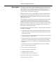
42CRC Color Registration Control Description The Photoswitch Type 42CRC Series 4000 LED Color Registration Mark Control with Automatic Gain Control (AGC) is a fixed focus diffuse-reflective scanning device designed to detect pre-printed registration marks against contrasting backgrounds. Detection of the marks is achieved by sensing the difference in the gray-scale response to the mark and background.
2CRC Color Registration Control 2 Description (Continued) S An external gate input makes it possible to blind the control during portions of the machine cycle, eliminating the possibility of false signals between registration marks. S Analog test points allow evaluation of mark contrast prior to running a machine, and three LED status indicators provide setup ease and accuracy. S Quick Disconnect design for ease of installation, reduced downtime and replacement cost. S NPN or PNP outputs.
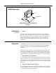
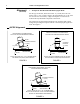
42CRC Color Registration Control 3 42CRC Mounting 42CRC WEB MATERIAL MOUNT THE 42CRC OVER A PLATE OR ROLL TO PREVENT FALSE SIGNALS DUE TO WEB FLUTTER FIGURE 1 Installation c. Wiring (Continued) For proper wiring the 42CRC requires a Photoswitch Cable Assembly #60-2292 ordered separately. The control operates on 10-30 VDC @ 70 mA max. See pages 11 and 12 for complete specifications. All external wiring should conform to the National Electric Codes and applicable local Codes.
42CRC Color Registration Control 4 Alignment c. Transparent Web Material With Dark Opaque Mark (Continued) For this type of material, mount the control .5 (13 mm) above the web surface and at a 10 to 15 degree angle to the perpendicular (75 to 80 from the control to the web surface). A light colored plate or roller must be mounted directly behind the transparent web material.
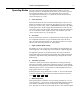
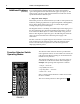
42CRC Color Registration Control Operating Modes 5 After the control has been installed and aligned, it must be set for the particular operation. An important feature of the control is that it gives the user complete flexibility to select any combination of the four major operating modes listed below via a convenient external function selector switch. See Figures 5, 6, and 7. a.
42CRC Color Registration Control 6 Operating Mode (Continued) level, and is easier to set up in the manual operation mode. The control must be set in the manual mode when the “test points” are used to check for sufficient sensing contrast (see “Contrast Check” on page 9.) In this position the orange LED marked “AUTO” will be “OFF” and the manual sensitivity adjustment is functional. Switch positions for this mode are B, B , D, D , F, F , H, H . f.
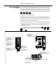
42CRC Color Registration Control 7 Function Selector Switch Operating Modes NON-LATCHED OUTPUT DARK MARK MANUAL SENSITIVITY GREEN LED LATCHED OUTPUT LIGHT MARK AUTOMATIC SENSITIVITY RED LED LATCHED OUTPUT DARK MARK AUTOMATIC SENSITIVITY RED LED LATCHED OUTPUT LIGHT MARK MANUAL SENSITIVITY RED LED NON-LATCHED OUTPUT LIGHT MARK MANUAL SENSITIVITY GREEN LED NON-LATCHED OUTPUT DARK MARK AUTOMATIC SENSITIVITY GREEN LED H G G F F NON-LATCHED OUTPUT LIGHT MARK AUTOMATIC SENSITIVITY GREEN LED NON-LATCHED OUT
42CRC Color Registration Control 8 Additional Features (Continued) To avoid detecting the unwanted marks, the control can be disabled “gated” during the times the unwanted marks appear (see Figure 9). The control can be “gated” by using electromechanical or solid state contacts synchronized with the machine cycle. c.
42CRC Color Registration Control Additional Features 9 d. Contrast Check (Continued) Test Points are provided on the back cover of the control (see Figure 5, Page 6) to determine if sufficient contrast exists between the mark and the background for reliable operation. The test point contacts are made of nickel plated stainless steel and can be immersed in water or short circuited without affecting the operation of the control. To check contrast, set the control in the manual mode.
42CRC Color Registration Control 10 Operation After the control has been properly installed and the chosen operating mode has been selected, set the dwell and the sensitivity controls to the full counter-clockwise position. Apply power to the control and set the web in motion. THE WEB MUST BE MOVING AT LEAST 2 INCHES (51 mm) PER SECOND FOR PROPER CONTROL FUNCTION. Automatic, Non-Latch In this setting no sensitivity adjustment is required and the sensitivity control is inoperative.
42CRC Color Registration Control Maintenance Specifications Clean the lens surface periodically. With a non-abrasive cleaning solution (mild soap) and a soft cloth. Do not use strong chemicals on the plastic lens.
12 42CRC Color Registration Control Voltage Supply: . . . . . . . . . . . . . . . . . . . . . . . . . . . . . . . . . 10V to 30VDC Current Consumption . . . . . . . . . . . . . . . . . . . . . . . . . . . . . . . 70mA Max. Output: Model 4000 . . . . . . . . . . . . . . . . . . . . . . . . . . . . . . Open Collector NPN (Current Sink) Model 4001 . . . . . . . . . . . . . . . . . . . . . . . . . . . . . . Open Collector PNP (Current Source) Output Rated Load Current (On-State) . . . . . . . . . . . . . . .
42CRC Color Registration Control Specifications (Continued) 13 Dimensions . . . . . . . . . . . . . . . . . . . . . . . . 3.80 L X 2.95 H X 1.31 D (97mm L X 75mm H X 33mm D) Weight . . . . . . . . . . . . . . . . . . . . . . . . . . . . . . . . . . . . . . . . . 12 oz (350 g) Storage Temperature . . . . . . . . . . . . . . . . --13F (--25C) to 167F (75C) Operating Ambient Temp. Range . . . . . . . . . 32F (0C) to 158F (70C) Max Relative Humidity . . . . . . . . . . . . . . . . . . . . . . . .
42CRC Color Registration Control 14 Outline Dimensions (mm between brackets) 2.500 (63.50) Using Optional Lens Position 1.312 (33.32) .656 (16.62) .419 (10.64) Focal Points (Scanning Distance) .470 (11.94) PHOTOSWITCH .375 (9.53) COLOR REGISTRATION CONTROL 42CRC--4000 SUPPLY OUTPUT 2.357 (59.87) 1.10 (27.94) 3.375 (85.73) .432 (10.97) 1.875 (47.63) 4D 30vDC 70MA MAX 100MA 30VDC MAX N.O. NPN 51NK 20MA 30VDC MAX ALARM SCANNING WHITE- GATE (- ) / RESET (+) ORANGE- DIAG.
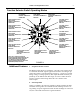
42CRC Color Registration Control 15 Diagnostic Alarm Minimum Resistor Value Selection 1000 MINIMUM RESISTANCE (OHMS) 833 667 500 333 0 (USE 1/2 WATT RESISTOR) 10 15 20 VOLTAGE (D.C.) 25 30 FIGURE 12 Color Coding #60-2292 Cable Assembly WHITE-GATE (--) / RESET (+) ORANGE-DIAG.
42CRC Color Registration Control 16 Wiring Diagrams NPN OUTPUT 42CRC -- 4000 Latched Output -- Function Switch Positions “A” Through “D” with or without External Gating External Connections 42CRC-4000 Cable Assembly #60-2292 Connector Red (+) (+) Supply 10-30VDC Load Blue--NPN Output Reset* Switch (close to unlatch) Control Output (NPN) Sink 30mA max, remote diagnostic indicator by customer (if used) Orange-NPN Diagnostic Alarm Diagnostic Output (NPN) Sink Resistor by customer (if remote diagnos
42CRC Color Registration Control 17 Wiring Diagrams (Continued) PNP OUTPUT 42CRC -- 4001 Latched Output -- Function Switch Positions “A” Through “D” with or without External Gating External Connections 42CRC-4001 Reset* Switch (close to unlatch) Cable Assembly #60-2292 Connector Red (+) Control Output (PNP) Source (+) Supply 10-30VDC Resistor by customer (if remote diagnostic indicator is used.) See Figure 12 for resistor selection.
42CRC Color Registration Control 18 Performance Curves Relative Sensitivity Vs Web Speed (Automatic Mode) 1.1 Relative Sensitivity 1 .6 .4 .2 2 7 10 70 100 700 1000 Speed (In/Sec.) (Metric Conversion 1 = 25.4mm) FIGURE 18 Relative Sensitivity Vs Web Speed (Manual Mode) 1.1 Relative Sensitivity 1 .8 .6 .4 .2 .5 .7 1 5 10 70 100 Speed (In/Sec.) (Metric Conversion 1 = 25.
GuardShield™ Safety Light Curtain User Manual 40 Original instructions R
GuardShield™ Safety Light Curtain User Manual 40 Original instructions R
GuardShield™ Safety Light Curtain User Manual 40 Original instructions R
PHOTOSWITCH is a registered trademark of Rockwell Automation. www.rockwellautomation.com Power, Control and Information Solutions Headquarters Americas: Rockwell Automation, 1201 South Second Street, Milwaukee, WI 53204-2496 USA, Tel: (1) 414.382.2000, Fax: (1) 414.382.