Allen-Bradley REC Resolver-toEncoder Converter (Cat. No. 4100-5.
Important User Information Because of the variety of uses for the products described in this publication, those responsible for the application and use of this control equipment must satisfy themselves that all necessary steps have been taken to assure that each application and use meets all performance and safety requirements, including any applicable laws, regulations, codes and standards.
x-3
Table of Contents Preface Read This Manual ................................................1 Who Should Use this Manual............................... 1 Purpose of this Manual......................................... 1 Safety Precautions ................................................2 Contents of this Manual .....................................3 Related Documentation ......................................3 Terminology .........................................................
ii Table of Contents Chapter 3 – Setup Chapter Objectives .............................................25 Setting the Rotary Switches ............................... 25 Configuration Switch A ...................................26 Configuration Switch B ...................................26 Powering the AEC.............................................. 27 AEC With GML Commander ............................28 Adding AEC to your Commander Diagram ....28 Setting the Transducer Resolution .................
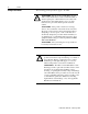
Preface Preface Read This Manual Who Should Use this Manual Read and understand this instruction manual. It provides the necessary information to let you install, connect, and set up the AEC for safe, reliable operation.
2 Preface Safety Precautions The following general precautions apply to the AEC: ATTENTION: Electric shock can kill. Make sure the AEC is safely installed in accordance with the Installation and Set-up chapters of this manual. Avoid contact with electrical wires and cabling while power is on. Only trained service personnel should open the electrical cabinet. ! ATTENTION: This product contains stored energy devices.
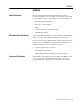
Preface 3 Contents of this Manual Chapter Title Preface 1 Overview 2 Installation 3 Set-Up Appendix Specifications A Contents Describes the purpose, background, and scope of this manual. Also specifies the audience for whom this manual is intended. Provides a general description of the REC, its features and mechanical specifications. Provides the steps needed to successfully mount and wire the REC to a Resolver and the S Class Compact Motion Controller or the 1394 GMC system.
4 Preface Resolver Package - An electrical mechanical device that has a single input shaft and one or more resolver elements. The resolver elements are geared to the input shaft. Common Techniques Used in this Manual The following conventions are used throughout this manual: • Bulleted lists such as this one provide information, not procedural steps. • Numbered lists provide sequential steps or hierarchical information. • Words that you type or select appear in bold.
Preface Allen-Bradley Support 5 Allen-Bradley offers support services worldwide, with over 75 Sales/ Support Offices, 512 authorized Distributors and 260 authorized Systems Integrators located throughout the United States alone, plus Allen-Bradley representatives in every major country in the world.
6 Preface Publication 999-126 - February 1996
Chapter 1 Overview REC Description The REC converts a single or dual (Master/Vernier) resolver input signal to an A Quad B quadrature encoder output signal. The A Quad B quadrature output signal can be directly connected to the 1394 GMC System module or the S Class Compact motion controller. In operation, the REC uses differential quadrature encoder output signals to send incremental position data to the motion controller based on the position of the resolver.
8 Overview REC Mechanical Specifications • The ability to be powered with a single18-36 V DC power supply. • Automatic resolver phase compensation for accurate position tracking. Figure 1.1 shows the placement and labeling of major items on the REC front panel. Figure 1.1 REC front panel 203.2 mm (8.0 in.) with cable clearance Use 1/4-20 or M6 bolt (typical 2 places) Reset Axis 0 OK Axis 1 OK 342.9 mm (13.5 in.) 330.2 mm (13.0 in.
Chapter 2 Installation & Hook-Up Chapter Objectives Read this entire chapter before beginning to mount, connect, or wire any of the components to the REC. It is the responsibility of the installer to see that the installation conforms to the directions in this manual and local codes and procedures. This chapter covers the following topics. • European Union Compliance • Mounting the REC. • Connecting the REC to the 1394 GMC system. • Connecting the REC to the Compact motion controller.
10 Installation & Hook-Up To meet CE requirements, the following are required: Mounting the REC • The REC must be mounted in an IP 54 rated metal enclosure on a metal panel. • All equipment must be bonded. • You must use the specified Allen-Bradley cables. • The REC is designed to function without maintenance when operated in the environment specified in this manual. • Under normal conditions, the REC should not require any periodic maintenance.
Installation & Hook-Up 11 Figure 2.1 Mounting and Grounding Diagram #10 AWG to Ground Bus REC Mounting Tab Ground Lug Internal Star Washers Size 1/4 - 20 or M6 Hardware Tapped Hole (Minimum of 3 Threads) Scrape paint off panel to insure electrical connection between chassis and grounded metal plate. Metal Panel (Must be connected to earth ground.) Mount the REC next to a 1394 GMC system or an S Class Compact motion controller on a metal enclosure panel using two 1/4 -20 or M6 bolts.
12 Installation & Hook-Up Figure 2.2 Mounting the REC next to a 1394 GMC on a system panel Wireway REC 1394 GMC System Reset Axis 0 OK A Optional Second REC for Axis 2 and 3 Axis 1 OK B Axis 0 Resolver Axis 0 Encoder Power & Drives Axis 1 Encoder A B Axis 1 Resolver REC Important: The REC can only be mounted on the left side (when looking directly at the mounted 1394) of the 1394 GMC System. This is due to cable specifications and module expansion of the 1394.
Installation & Hook-Up 13 Figure 2.3 Mounting the REC next to an S Class Compact motion controller.
14 Installation & Hook-Up ! ATTENTION: The REC does not support the removal or the insertion of any connectors when under power. The power disturbance can result in unintended machine motion, loss of process control, or an electrical arc that can cause an explosion in a hazardous environment. Connecting the REC to the 1394 Connect the REC to a 1394 GMC System using the encoder cable (catalog number 1394-GR04) for each axis.
Installation & Hook-Up 15 Figure 2.4 Connecting the Encoder Cables and the 5V Power Supply to the 1394 Wireway REC 1394 GMC System Reset Axis 0 OK A Axis 0 Encoder Connector Axis 1 OK B 1394-GR04 Axis 0 Resolver Axis 0 Encoder Axis 1 Encoder Connector Power & Drives Axis 1 Encoder 5V DC Power Supply A B Axis 1 Resolver REC Important: Anchor the cable so that no more than 2 feet of cable is left unsupported.
16 Installation & Hook-Up Figure 2.
Installation & Hook-Up 17 Figure 2.6 Terminal diagram Terminal open Clamping screws Terminal closed 2. Table 1: Terminal Steps If the terminals are: Do this: Not open Go to step 3 Open Go to step 4 3. Using a small, flat-head screwdriver, turn the clamping screw counter-clockwise several times. 4. Using a proper stripping tool, strip the wire insulation back on the cable lead. Important: All terminals accommodate a maximum of 14 gauge wire. 5. Trim the cable lead so that 0.
18 Installation & Hook-Up Figure 2.7 Wiring a 1326AB-MOD-VD:256 Master/Vernier Dual Resolver package to the Axis 0 Resolver plugs or the Axis 1 Resolver plugs on the REC. Plug A Plug B Green N Black R 20 19 18 16 15 14 Violet M Black P 7 Blue J Black K 5 6 4 Orange E Black G Resolver Assembly 1326AB-MOD-VD :256 White A Black B 3 13 2 12 11 9 Red D Black F 8 17 Axis Fault N.O.
Installation & Hook-Up 19 Figure 2.9 Wiring an 846-SJxxxx-R2-x single resolver package to the Axis 0 Resolver plug or the Axis 1 Resolver plug on the REC Plug A Plug B Green E Black G 20 19 18 16 White A Black B 15 14 7 6 5 4 3 13 2 12 11 846-SJABCD-R2-E Resolver Assembly 9 8 Red D Black F 17 Axis Fault N.O. 10 Chassis Ground 1 Chassis Ground 845AB-CA-i-xx Cable Internal fault relay contact Important: Anchor the cable so that no more than 2 feet of cable is left unsupported.
20 Installation & Hook-Up Figure 2.10 Connecting the Resolver Cable to the REC Wireway REC Axis 0 resolver connector Reset Axis 0 OK A Axis 1 OK B Axis 0 Resolver Axis 0 Encoder Power & Drives Axis 1 resolver connector Axis 1 Encoder A B Axis 1 Resolver REC To Resolver 1 To Resolver 0 Important: Anchor the cable so that no more than 2 feet of cable is left unsupported. The excessive weight of an unanchored cable could pull the plug out of the connector.
Installation & Hook-Up 21 Important: You must use both 5-position plugs when you power-up the REC. We recommend you use twisted, shielded wire that is UL listed. Refer to local wiring codes for more information. Power Supply Requirements Use a 12W power supply with 24V DC output to power the REC. Use a larger supply if you want to run multiple RECs or other devices. Figure 2.11 shows where to connect the power supply ot the REC.
22 Installation & Hook-Up Wiring the Drives Signal for a Compact When using the REC with an S Class Compact, the drive reference signals (+/-10V) are passed from the Compact to the REC at terminals 8, 9, and 10 on plug A (Axis 1), and at terminals 3, 4, and 5 on Plug B (Axis 0). To wire the drives signal: 1. Connect the drive signal to the servo amplifier using a twisted, shielded cable (Belden 9501 or equivalent). 2. Wire the cable leads to the appropriate Power & Drives plugs ofr the required axis.
Installation & Hook-Up 23 The relay output can be used to disable external devices or incorporated into your machine’s E-stop string (or other protective circuitry) for fail-safe protection. The REC provides Form_C (Normally Open) contacts to disable external equipment in the event of a malfunction. Important: Both the fault relay and the LED (Axis OK) are activated during normal operation and deactivated during a malfunction.
24 Installation & Hook-Up Figure 2.14 Typical Fault Relay for Switching AC DC Common The REC Fault contact is located at the Axis 0 and Axis 1 resolver connector 24V DC 11 1 K AC Common AC Hot Start Stop Start/Stop String CR1 K Fault String CR1 We recommend that you use an external relay controlled by the REC fault relay when you switch AC. The fault connections shown above are typical. You can modify them to fit the requirements of your application.
Installation & Hook-Up 25 The 1394 GMC System and S Class Compact motion controller have an encoder loss circuit that detects when the encoder drivers are disabled. When the REC faults: • The REC disables the encoder drivers. • The REC signals an encoder loss fault ot the controller. Important: The Transducer Loss Detection feature is an option in the Edit Axis window in GML. We recommend that you keep the transducer loss detection feature enabled in the motion controller.
26 Installation & Hook-Up Publication 999-126 - February 1996
Chapter 3 Setup Chapter Objectives Adding the REC to your GML Diagram The REC was designed to complement the 1394 GMC System or the S Class Compact motion controller and not intended to be used as a stand-alone product. This manual assumes that you are running GML (Graphical Motion Language) version 3.81 or greater and using Firmware 3.3 or greater. This chapter contains the information you need to: • Configure the motion controller using GML. • Align resolver packages.
26 Setup Setting the Transducer Counts per Motor Revolution for the 1394 You have to adjust the Transducer Counts per Motor Revolution parameter when you use an external transducer to close the servo position loop. This parameter is used to scale internal variables for tuning the axis. With the Axis Configuration edit window open, set the transducer counts per motor revolution. To set the transducer counts per motor revolution: 1. From the Configuration menu, select Drive/Motor 1394.
Setup 27 2. If your system uses a: Select: Single resolver package Absolute Dual resolver package Absolute_MV If you select Absolute_MV, an Assembly Part # menu that contains a list of supported Allen-Bradley dual resolver part number appears. Note: Currently, the REC supports the 1326AB-MOD-VD 256/255 dual resolver package. The Custom menu choice ( located in the Assembly Part # menu) allows you to enter a custom master/vernier dual resolver turns range.
28 Setup On-Line Axis Setups Axis hookup and servo parameters can be readily handled through the GML On-Line Manager Setup functions. For example, the Motor/ Encoder Test and the Align Absolute Transducer procedure are just two of the functions that can be controlled using GML. The On-Line Manager provides you with an interactive means of setting up your motion controller axes. The sections below show how to use these functions to help setup the REC.
Setup 29 5. Select Motor/Encoder Test. A black circle appears in the radio dial next to the text. 6. Select Execute. Refer to your GML Programming Manual and your motion controller’s Installation and Setup/User Manual for more information on Motor/Encoder Tests. Aligning the Absolute Transducer After you have completed the Motor/Encoder Test, you need to align the resolver package position to the axis position.
30 Setup For Example: Assume the actual position of the absolute transducer is 1 at the alignment point. After alignment, the home position (home offset) variable equals -1. Therefore, the axis position is defined as 1 + (-1) = 0. Assume the axis is moved one unit and the position of the absolute transducer is now 2. If you execute a home command at this point, the axis position is 2 + (-1) =1.
Setup 31 1. While still in the Enter Setups window, select Tuning Complete, Save Data/Update Diagram. 2. Select Execute. The diagram updates and the Do Setups window disappears. 3. Select Exit Online. The Online Manager window disappears. Homing the Axis The motion controller executes a home command to determine the absolute position of the resolver package. To execute the home axis command: 1. Double click on the Home Axis block in your GML diagram. 2. Select Wait for Completion.
32 Setup If the travel range was defined to be 0 =< travel <256 and the axis homed, after moving it slightly negative of the (zero) position, the controller would think that the axis was near 256 instead of near zero. The internal travel range allows the axis to dither about zero by -5 turns thus eliminating unwanted roll over at the alignment position. If you homed the axis after moving it slightly negative of -5 the axis position would roll over to just less than 251.
Setup 33 3. Select the axis you are configuring. The name of the axis appears in the field. 4. Select Relative from the Mode menu. The word Relative appears in the field. Note: This feature compensates for any dither that may occur while executing the program 5. Select Actual from the Position menu. The word Actual appears in the field. 6. Enter a positive or negative value to redefine the current actual position. Note: If the axis was previously aligned to zero, the actual position is zero. 7.
34 Setup Publication 999-126 - February 1996
Appendix A Specifications Figure A.6 AEC Front Panel Figure A.1 shows the terminal locations for the REC. The following tables provide the pin numbers and their respective descriptions. Important: Refer to Wiring Axis 0 and Axis 1 Resolvers for wiring your Allen-Bradley resolver package to the REC.
38 Encoder Connector Terminal Descriptions The table below shows the terminal descriptions for Axis 0 and Axis 1.
39 Specification Description 1326AB-MOD-VD1:x single resolver package. x = rotor to input shaft ration x = 1, 2, 2.5, or 5 1326AB-MOD-VD:256/255 dual resolver package. 256/255 is the master to vernier gear ratio. Use cable 1326AB-CVUxx for the specified Bulletin 1326 resolver packages above. xx = length in feet (100 ft. maximum) Supported resolver packages 846-SJ abcd-R2-e single resolver package.
40 A B Z Important: The marker pulse is synchronized to the resolver element’s zero position which is not necessarily the axis zero position. Power Supply Specifications The table below details the electrical specifications of the power supply.
41 Excitation Oscillator The table below details the product performance of the excitation oscillator for the REC. Specification Description Excitation Frequency 4000Hz at +25% Amplitude 4.77V rms +5% Phase Loss Detection The table below details the product performance of the phase loss detection circuit for the REC. Specification Purpose Description To detect loss of resolver signals. When fault occurs: • The status indication LED turns from green to red • The 30V DC 2A/125V AC 0.
42 Publication 4100-5.
Index Index A Absolute Position Update, 31 Absolute Strobe Cycle, 43 Absolute Strobe Timing, 44 C CE requirements, 10 Configuration GML Commander Adding to a Commander Diagram, 28 Aligning Absolute Encoder, 29 Selecting Homing Procedure, 29 Setting the Transducer Resolution, 28 Connecting the AEC to the 1394, 14 to the Compact, 15 D Definitions encoder, 4 transducer, 3 Description, 7 E European Union Directives EMC Directive, 9 F Fault Indication Encoder Faults, 34 Internal Faults, 35 No Faults, 35 Transdu
48 Index Allen-Bradley, 5 local product, 5 technical product assistance, 5 W Wiring Cable Flying Leads, 16 Control Connector Analog Servo, 21 Fault Relay 19 Power Supply, 22 SSI Connector, 18 Publication 4100-5.
Allen-Bradley, a Rockwell Automation Business, has been helping its customers improve productivity and quality for more than 90 years. We design, manufacture and support a broad range of automation products worldwide. They include logic processors, power and motion control devices, operator interfaces, sensors and a variety of software. Rockwell is one of the world’s leading technology companies. Worldwide representation.