ALEC AxisLink Encoder Converter Cat No. 4100-5.
Important User Information Because of the variety of uses for the products described in this publication, those responsible for the application and use of this control equipment must satisfy themselves that all necessary steps have been taken to assure that each application and use meets all performance and safety requirements, including any applicable laws, regulations, codes and standards.
European Communities (EC) Directive Compliance If this product has the CE mark it is approved for installation within the European Union and EEA regions. It has been designed and tested to meet the following directives.
Table of Contents Preface Read This Manual Read This Manual . . . . . . . . . . . . . . . . . . . . . . . . . Who Should Use this Manual. . . . . . . . . . . . . . . . . Purpose of this Manual . . . . . . . . . . . . . . . . . . . . . Safety Precautions . . . . . . . . . . . . . . . . . . . . . . . . . Terminology . . . . . . . . . . . . . . . . . . . . . . . . . . . . . Common Techniques Used in this Manual . . . . . . . ALEC Product Receiving and Storage Responsibility Allen-Bradley Support . . . . . .
ii Chapter 3 Setup Chapter Objectives . . . . . . . . . . . . . . . . . . . . . . . . . . . . . . . 27 Setting the Rotary Switches . . . . . . . . . . . . . . . . . . . . . . . . . 27 Selecting the Operation Mode . . . . . . . . . . . . . . . . . . . . 27 Selecting the AxisLink Address . . . . . . . . . . . . . . . . . . . . 28 Selecting the Options Configuration . . . . . . . . . . . . . . . . 29 Encoder Power (12V 5V) . . . . . . . . . . . . . . . . . . . . . . . . . . .
iii DIP Switches . . . . . . . . . . . . Resetting the Encoder Mode . Encoder OK LED . . . . . . . . . Fault Relay . . . . . . . . . . . . . Index . . . . . . . . . . . . . . . . . . . . . . . . . . . . . . . . . . . . . . . . . . . . . . . . . . . . . . . . . . . . . . . . . . . . . . . . . . . . . . . . . . . . 48 49 49 50 Index . . . . . . . . . . . . . . . . . . . . . . . . . . . . . . . . . . . . . . . . . 51 Publication 4100-5.
iv Publication 4100-5.
Preface Read This Manual Read and understand this instruction manual. It provides the necessary information to let you install, connect, and set up the ALEC for safe, reliable operation.
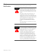
Preface 2 Safety Precautions The following general precautions apply to the ALEC: ATTENTION ! Electric shock can kill. Make sure the ALEC is safely installed in accordance with the Installation and Set-up chapters of this manual. Avoid contact with electrical wires and cabling while power is on. Only trained service personnel should open the electrical cabinet. This product contains stored energy devices.
Preface 3 Contents of this Manual Chapter Title Preface 1 Overview 2 Installation & Hookup 3 Set-Up 4 Fault Indication & Control Status Appendix A Specifications Appendix B Upgrading From ALEC Series C to ALEC Series D Contents Describes the purpose, background, and scope of this manual. Also specifies the audience for whom this manual is intended. Provides a general description of the ALEC, its features and mechanical specifications.
Preface 4 AxisLink - is an IMC S Class option which links multiple motion controllers and ALECs to provide real-time axis coordination between their axes in distributed multi-axis system. Virtual Axis - An axis on one motion controller, which is linked to an axis on another motion controller or ALEC via AxisLink. Common Techniques Used in this Manual The following conventions are used throughout this manual: • Bulleted lists such as this one provide information, not procedural steps.
Preface 5 Leave the product in its shipping container prior to installation.
Preface 6 Publication 4100-5.
Chapter 1 Overview ALEC Description The ALEC is a single-axis AxisLink Encoder Converter which interfaces a single incremental encoder to Allen-Bradley IMC S Class motion controllers via AxisLink. As such, it provides a master encoder input for IMC S Class motion controllers or 1394 GMC systems without the need to sacrifice a full servo axis for use as a master encoder input. The ALEC also allows easy remote location of the master encoder for connection to an existing machine.
8 Overview The optically isolated encoder input accepts 5 Volt differential quadrature signals from standard incremental encoders. 5V and 12V DC are available from the ALEC for powering the encoder. An optically isolated registration input which latches encoder position is provided for direct interface to a position registration sensor. This input can be used directly with 5V or 24 V devices. AxisLink communication with IMC S Class motion controllers is controlled by a dedicated communication chip.
Overview Package size mm and (in.) Product weight kg and (lbs.) Material 9 Package Specifications 300.23 x 130.175 x 48.26 (11.82 x 5.125 x 1.9) 1.68 (3.69) Painted Steel Publication 4100-5.
10 Overview Publication 4100-5.
Chapter 2 Installation & Hook-Up Chapter Objectives Read this entire chapter before beginning to mount, connect, or wire any of the components to the ALEC. It is the responsibility of the installer to see that the installation conforms to the directions in this manual and local codes and procedures. This chapter covers the following topics. • • • • • • • • • Installing the ALEC European Union Compliance. Mounting the ALEC. Connecting AxisLink. Connecting the Encoder. Allen-Bradley Encoders.
12 Installation & Hook-Up EMC Directive The ALEC is tested to meet Council Directive 89/336 Electromagnetic Compatibility (EMC) in accordance with Article 10 (1). The following directives apply: • EN 50081-2 EMC-Generic Emission Standard, Part 2-Industrial Environment. • EN 50082-2 EMC-Generic Immunity Standard, Part 2-Industrial Environment.
Installation & Hook-Up ATTENTION 13 To avoid a shock hazard, remove all power to the system panel before mounting the ALEC. ! The mounting tabs should be bolted firmly to the metal enclosure. The following diagram shows the proper method of mounting to make sure the ALEC is grounded. Figure 2.
14 Installation & Hook-Up See the “Setup” Chapter in this manual for instructions on setting these switches. The following section details how to wire the : • • • • • Wiring the ALEC AxisLink cable Incremental Encoder Registration Input Power connector Fault Relay There are several connectors on the front of the ALEC.
Installation & Hook-Up 15 1. Table 2.1 Terminal Steps If the terminals are: Do this: Not open Go to step 3 Open Go to step 4 2. Using a small, flat-head screwdriver, turn the clamping screw counter-clockwise several times. 3. Using a proper stripping tool, strip the wire insulation back on the cable lead. IMPORTANT All terminals accommodate a maximum of 14 gauge wire. 4. Trim the cable lead so that 0.275 inches of metal wire is exposed. 5. Insert the cable lead in the appropriate terminal.
16 Installation & Hook-Up Figure 2.3 Wiring the AxisLink Connector 150 Ω * Standard Length Blue 1 Shield 2 AxisLink Cable Clear 300 Ω * AxisLink Wiring A-B 1770-CD Belden 9463 Extended Length Yellow 1 Shield AxisLink Cable 2 Black Carol C8014 Belden 9182 *Install termination resistor only if this is the first or last module on the AxisLink line. IMPORTANT Anchor the cable so that no more than 2 feet of cable is left unsupported.
Installation & Hook-Up 17 Connecting the Encoder Encoders are connected to the ALEC using a supplied cable assembly. Two encoder cable assemblies are available as shown in the following table. Table 2.3 ALEC Encoder Cable Assemblies Order Number Length 4100-CAE15 15 feet (4.5 meters) 4100-CAE30 30 feet (9 meters) The encoder cable assemblies shown in the preceding table are electrically identical. The only difference is their length.
18 Installation & Hook-Up all the way to the right for 5V encoders. See the “Setup” chapter in this manual for information on selecting the encoder voltage. ATTENTION ! The required mode must be selected before applying power to the ALEC. Improper voltage applied to the encoder can cause damage to the encoder, the ALEC, and to the operator.
Installation & Hook-Up 19 Table 2.5 ALEC Connections for AB 845K Encoders ALEC Signal 4100-CAExx Wire Color Encoder Wire Color Encoder Signal Power Common Red Black Red Black B+ Input B+ Return Allen-Bradley 845P Encoders If you are using an Allen-Bradley 845P-SHC14-xx3 incremental encoder, use the following table for your connections. Table 2.
20 Installation & Hook-Up Connecting a Registration Sensor The ALEC provides a high-speed optically isolated registration input. If required in your application, this input can be used to latch the position of the encoder when the registration sensor is activated. The registration input requires 2.5 mA at 5V DC or 24V DC to operate.
Installation & Hook-Up 21 Figure 2.6 Current-sourcing Registration Sensor Power Supply − + 5V Current-sourcing Registration Sensor Supply * Output 24V - Common *Use 5V terminal and 5V power supply for 5V sensors. Use 24V terminal and 24V power supply for 24V sensors. Recommended cable is Belden 9501 or equivalent. The connections shown in the figures are typical.
22 Installation & Hook-Up making them more susceptible to interference. For these devices, the ON current can be raised by a shunt resistor across the registration input, as shown in the following diagram. Figure 2.7 ALEC Terminal Block ALEC AxisLink Terminal Block 470 , 2W 24V Normal 24V Registration Connections - IMPORTANT Where high levels of repetitive noise is unavoidable, Normally Closed sensors can offer improved immunity.
Installation & Hook-Up 23 The pin layout and functionality for this connector are shown in the following table. Table 2.7 Power Supply/Fault Relay Pin Functions Power Supply Pin Position from Top Pin Function 1 Common 2 Power (18-36V DC) 3 Fault N/O Relay Contact 4 Reference - The following diagram illustrates the power connections for the ALEC. IMPORTANT Power Common is internally connected to chassis. Figure 2.
24 Installation & Hook-Up sure you correct the wiring before replacing the fuse with a 2A Slow Blow, 1/4 x 1 1/4 fuse of the same type for continued protection. ATTENTION Do not apply power to the ALEC until the Mode switch is set correctly and all other connections have been made. ! Fault Relay To provide safe operation (opening the fault string if a fault occurs or power to the ALEC is lost) the fault relay outputs must be connected appropriately.
Installation & Hook-Up 25 A typical fault detection scheme may require additional circuitry when used in applications where the ALEC fault contacts do not have sufficient capacity to drive a fault detection circuit directly. Publication 4100-5.
26 Installation & Hook-Up Publication 4100-5.
Chapter 3 Setup Chapter Objectives The ALEC is used in conjunction with the 1394 GMC System or the S Class Compact motion controller and an encoder. It is not a stand-alone product and must be configured to work with the hardware connected to it. This involves specific steps that are determined by the make and model of the hardware connected to the ALEC. This manual assumes that the GML Commander v4.01 or higher software is used.
28 Setup ATTENTION The update rate for the ALEC must match the servo rate for the motion controller. ! The following table lists the switch setting and its accompanying frequency. IMPORTANT Switch positions 8 through F are reserved by Allen-Bradley for future use. Table 3.
Setup 29 Extended AxisLink then the ALEC can make use of any of the settings available on the AxisLink Address rotary switch. IMPORTANT In Standard AxisLink only switch settings 0 through 7 are available for use. Selecting the Options Configuration Located on the front panel of the ALEC are 6 DIP switches for setting the operating options. These six DIP switches determine the way the ALEC operates.
30 Setup Encoder Fault (Enc. Fault On/Off) This DIP switch (number 3) enables or disables the encoder fault. When the switch is in the On position (switch set to left), Encoder Fault is enabled. This means that when the ALEC detects a loss of encoder signal, the Encoder OK LED goes off, the CPU OK LED goes off, and the Fault Relay is opened. If the switch is in the Off position (switch set to the right), the Encoder fault is disabled.
Setup 31 Extended versus Standard AxisLink AxisLink has two modes of operation: Standard and Extended. In standard mode the maximum AxisLink cable length for the connected modules is limited to 85 feet (25 meters). In extended mode modules can be connected as needed on the AxisLink cable for up to 410 feet (125 meters). The number of modules that can be connected to AxisLink is limited to 8 in standard addressing mode where in extended addressing mode 16 modules may be connected. Table 3.
32 Setup Table 3.3 Alec Modes for Use with Allen-Bradley Encoders For Allen-Bradley Encoder Model Set Mode Switch to Set DIP Switch 1 for Encoder Voltage 845F-SJxZ14-xxYx... 845F-SJxZ24-xxYx... 0-7 0-7 5V 12V 845H-SJxx14xxyx... 845H-SJxx24xxYx... 0-7 0-7 5V 12V 845K-SAxZ14-xxY3 845K-SAxZ24-xxY3 0-7 0-7 5V 12V 845P-SHC14-xx3 0-7 5V 845T-xx12Exx... 845T-xx13Exx... 845T-xx42Exx... 845T-xx43Exx...
Setup ATTENTION ! Powering the ALEC 33 Check the status of other devices connected to the same AxisLink cable before pressing the Reset button on the ALEC. After setting the Mode and AxisLink Address switches and making the necessary connection as described in the installation section of this manual, you can apply power to the ALEC. The CPU OK and AL LEDs should turn green after applying power to the ALEC. Green LEDs indicate that it is working properly.
34 Setup ALEC With GML Commander The ALEC is used with a GML Commander configured for AxisLink or Extended AxisLink. Before Commander can download a diagram to the ALEC, the Mode rotary switch must be set to the same servo update rate as any motion controllers or other ALECs connected to the same AxisLink cable. The AxisLink Address rotary switch on the ALEC must be set, and the proper settings must be in place on the ALEC’s DIP switches.
Setup 35 10. Download the diagram. IMPORTANT AxisLink is not enabled until the diagram is downloaded. Once AxisLink is enabled, the AL LED should be green. If the AL LED is red, reset the ALEC by pressing the Reset button on the front panel of the ALEC box. If the AL LED stays red after re-setting, check the cabling and termination to make sure all of the wiring is done properly. If it remains red, call Allen-Bradley Technical Support.
36 Setup Publication 4100-5.
Chapter 4 Fault Indication & Control Status Chapter Objectives This chapter covers the ALEC operation status. There are three status LEDs on the front panel of the ALEC. These LEDs provide “at-a-glance” monitoring of the system. The three LEDs monitor different aspects of the ALEC/AxisLink system. The LEDs are labeled: AL, CPU OK, and Encoder OK. The following LEDs and status conditions are covered in this chapter.
38 Fault Indication & Control Status cause other control devices to work erratically which could cause machine damage or personal injury. ATTENTION ! Pressing the Reset Button on the ALEC can result in erratic behavior in other attached control devices. This can create a dangerous situation for both the machine and the operator. AxisLink Fault The ALEC indicates AxisLink faults by a RED AL LED. In a fault condition, there have been at least 256 link errors and AxisLink has shut down.
Fault Indication & Control Status 39 No Fault A green AL LED indicates AxisLink is running properly. This is the normal condition after power up and while the link is working. Table 4.1 AL LED Status Indicators AL LED Status Condition RED AxisLink Fault At least 256 link errors AxisLink Shuts Down FLASHING RED/ GREEN AxisLink Failing At least 96 link errors AxisLink is in danger of faulting.
40 Fault Indication & Control Status Publication 4100-5.
Appendix A Specifications Figure A.1 ALEC Front Panel Figure A.1 shows the front panel layout showing the dip switches, pin locations, rotary switches, and LEDs for the ALEC. The following tables provide explanations for the rotary switches, dip switches, and pins. Reset AL AB CD CPU OK 6 789 0 EF 1 2 3 45 AB CD Switch Setting 0 EF 1 2 3 45 6 789 1 2 3 4 5 6 AxisLink Table A.1 Mode Rotary Switch Settings Mode AxisLink Address 12V/5V Extd Node On/Off Enc.
42 Specifications DIP Switches numbered 4, 5, and 6 must all be set to the same position. ATTENTION ! Table A.3 AxisLink Connector Pin location Standard Length Extended Length Top Blue Black Middle Shield Shield Bottom Clear Yellow Table A.4 Incremental Encoder Connector Z- Z+ B- B+ A- A+ Common Encoder Power Shield (Chassis) Reserved Reserved Reserved Table A.5 Mechanical Specifications Publication 4100-5.
Specifications 43 Table A.6 Environmental Specification Specification Description Operating Temperature 0 to 50 o C Storage Temperature -40 to 85 o C Humidity 95% non condensing @ 50 o C Table A.7 Electrical Specifications Specifications Descriptions Power Input 18 - 36 Volts DC; 12 Watts maximum Fuse 2A Slow Blow, 1/4 x 1 1/4 Protection Reverse voltage via front panel fuse Table A.
44 Specifications Table A.8 Encoder Input Specifications Specification Description Encoder Minimum Voltage +/- 3.0V differential (A - A\, B - B\) Input Impedance (see Encoder Input Equivalent Circuit diagram, figure A.6) Encoder Power 5V DC or 12V DC +/- 4% at 0.5A maximum available from ALEC Table A.
Specifications 45 Table A.10 AxisLink Specifications Equivalent Circuit Diagrams Specifications Descriptions Standard Length Descriptions Extended Length Maximum Number of Nodes 8 with Standard Address; 16 with Extended Address 8 with Standard Address; see table in Extended Versus Standard AxisLink in the Setup chapter of this manual.
46 Specifications Figure A.2 Encoder Input Equivalent Circuit 6k 400 pF + A+ or B+ or Z+ * 330 - A- or B- or Z6k 400 pF * Includes encoder loss detection circuitry on A and B quadrature channels. This value is 10.5k for Marker (Z) Channel. Figure A.3 Registration Input Equivalent Circuit 5V 6k 2k 24V * 470pF 400 pF * Forward voltage drop of optocoupler diode Publication 4100-5.3 - June 1999 1.
Appendix B Upgrading From ALEC Series C to Series D The ALEC Series D has undergone some changes that affect the mounting, wiring, and configuring of the ALEC when upgrading from an ALEC series C to an ALEC series D. Summary of Changes Physical Dimensions The length and width of the box have seen no appreciable difference in size. The depth of the box has the greatest significance. The ALEC series C has a depth of 4.5inches (114 mm) and the ALEC series D has a depth of 5.125 inches (30.175 mm).
48 Upgrading From ALEC Series C to Series D Table B.1 Comparative Frequency Values Switch Setting ALEC Series C ALEC Series D 9 250 Hz Reserved A-F Not available Reserved The Mode switches in the Series D no longer control the encoder power output voltage. The Encoder Output voltage is now controlled by the position of DIP switch 1. (See the section on DIP switches in the Setup chapter of this manual.
Upgrading From ALEC Series C to Series D 49 Resetting the Encoder Mode The following table shows the differences between series C and series D for setting the switches for the update frequency and the output voltage for the encoder. Table B.
50 Upgrading From ALEC Series C to Series D Fault Relay The power connector has been enlarged to contain two more pins. The top two pins are used for connecting power and the bottom two pins are for connecting a fault relay. For more detailed information about any of the changes made to the ALEC series D, review the material in this manual. Publication 4100-5.
Index A AL LED 37 ALEC With GML Commander 34 Allen-Bradley Support 5 AxisLink Address rotary switch 48 AxisLink Failing 38 AxisLink Fault 38 F Fauilts AxisLink no fault 39 Fault Relay 24 faults AxisLink faulted 38 Features, 7 Fuse, 33 C CE requirements 12 Commander AxisLink Configuration 34 Comparative Frequency Values 47 Comparative Switch Settings 49 Configuration GML Commander Adding to a Commander Diagram, 34 Connecting a Registration Sensor 20 Connecting AxisLink 15 Connecting the ALEC 13 Connecting
52 Index Environmental 43 Incremental Encoder Connector 42 Mechanical 42 mechanical 8 Mechanical, Mode Rotary Switch Settings 41 Package, 9 Registration Input 44 Specifications Encoder input 43 Summary of Changes AxisLink Address Rotary Switch 48 Encoder OK LED 49 Fault Relay 50 Mode Rotary Switch 47 Physical Dimensions 47 Publication 4100-5.
Back Cover Publication 4100-5.3 - June 1999 54 Supersedes Publication 4100-5.3 -July 1998 © 1999 Rockwell International Corporation. Printed in the U.S.A.