
Instruction Manual


21.
Replace the outlet air duct over the nine loosened
hex
head
cap screws making sure all wiring is clear of
the
duct. Tighten the screws.
22. Using the hardware supplied with the Contactor,
reconnect
motor leads T1, T2 and T3 to terminals 1T1,
1T2, and 1T3, respectively, on the load side of the
Contactor.
23. Using the two supplied spacers, the two 1/4Ć20 x 1
1/4"
hex head cap screws, and the two remaining 1/4"
flat washers and 1/4" lock washers; install the Cover
(705321Ć15R) on the Contactor.
24. ReĆapply power the AĆC VLS Drive.
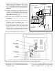
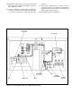
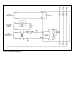
Figure 6. Connecting Wire Harnesses 801553Ć34R and Ć35R.
CONTACTOR
CONTROL
TRANSFORMER
FUSE
RELAY
TB1
REGULATOR
WIRE
HARNES
S
801553Ć34R
AUXILIARY
CONTACT
WIRE HARNES
S
801553Ć35R