
Instruction Manual


1. Disconnect all power to the AĆC VLS Drive before
installing this kit.
DANGER
EQUIPMENT IS AT LINE VOLTAGE WHEN
THE
INPUT DISCONNECT IS ON. THE
INPUT
DISCONNECT MUST BE OFF BEFORE IT IS
SAFE
TO TOUCH ANY INTERNAL P
ARTS
OF
THIS EQUIPMENT. AFTER POWER IS
REMOVED, THE COMMUTATION CAPACIĆ
TORS CAN REMAIN CHARGED. ALLOW
TWO MINUTES BEFORE TOUCHING ANY
INTERNAL PARTS OF THE CONTROLLER.
FAILURE TO OBSERVE THESE PRECAUĆ
TIONS COULD RESULT IN FATAL INJURY.
NOTE: If the Output Contactor Kit and the Control Circuit
Transformer Kit are to be installed, mount the Output
Contactor
Kit first because the
Control Circuit T
ransformer
Kit normally occupies the same location as the Output
Contactor Kit. The Control Circuit Transformer
Kit must be
relocated as defined in Instruction Sheet D2Ć3014.
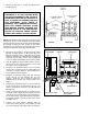
2. Disconnect
motor leads T1, T2 and T3 from the output
bus bar assembly (Figure 1). Disconnect bus bars
601, 602 and 603 from the output bus bar assembly
(Figure 1). Remove the output bus bar assembly by
removing the four taptite screws. This assembly will
not
be used while the Output Contactor
Kit is installed.
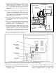
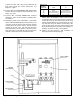
3.
Snap the Auxiliary Contact (76624Ć
X) into the cavity on
the front left of the Contactor (Figure 2). Secure with
the captive lock screw provided.
4. Using the four furnished 5/16Ć18 x 1/2" hex washer
head
screws, mount
the Contactor (705310Ć9R) in the
controller as shown in Figure 2. The mounting holes
are preĆdrilled in the back panel.
5. Using the six furnished 1/4Ć20 x 3/4" hex head cap
screws and six 1/4" flat washers and 1/4" lock
washers, install the three identical Connectors
(610290Ć57A) to the line side of the Contactor. See
Figure 2.
6. Using
the three furnished 1/2Ć13 x
1 1/4" hex head cap
screws and the three 1/2" flat washers and 1/2" lock
washers, attach the Connectors to the 601, 602 and
603 bus bars.
7. Using
four of the furnished 10Ć32 x 1/2" taptite screws,
mount the Control Transformer (417155ĆS) to the left
of
the motor overload relay block as shown in Figure 2.
The
mounting holes are preĆdrilled in
the back panel.
(It might be helpful to preĆthread the screws in the
mounting holes.)
8. connect the metal jumper supplied with the
transformer
between the two center
terminals (H
3
and
H
2
)
on the input side of the transformer
. See Figure
2.
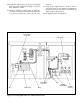
Figure 1. Removing output bus bar assembly.
Figure 2. Controller right bay components.
FUSE
IN FUSE BL
OCK
METAL
JUMPER
MOTOR OVERL
OAD
RELA
Y BL
OCK
CONNECTOR (3)
CONTACTOR
AUXILIARY
CONTACT
CONTROL
TRANSFORMER
OUTPUT
BUS BAR
ASSEMBLY
SIDE VIEW
FRONT VIEW
TAPTITE
SCREW (4)
DISCONNECT MOTOR
LEADS T1, T2, T3
BUS BARS
601, 602, 603