
Instruction Manual


INSTRUCTION SHEET D2Ć3017Ć2
OUTPUT
CONT
ACTOR KIT
Models 36C47
F
or use with 300, 350, 400 and 500 HP
460 V
AC, ThreeĆPhase Input
General Purpose or Variable Torque
AĆC VLSR
Drives
WARNING
BEFORE INST
ALLING
AND/OR
OPERA
TING
THIS KIT, THE QUALIFIED ELECTRICAL
MAINTENANCE
PERSON WHO IS F
AMILIAR
WITH THIS TYPE OF EQUIPMENT AND THE
HAZARDS INVOLVED SHOULD READ THIS
ENTIRE INSTRUCTION SHEET. FAILURE
TO
OBSERVE THIS PRECAUTION COULD REĆ
SULT IN BODILY INJURY.
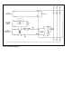
DESCRIPTION
The Reliance Electric Output Contactor Kit provides a
positive
disconnect (contactor) between the output of the
AĆC VLSR Drive Controller and the Drive Motor. A
controller Start command will cause the contactor to be
energized.
The controller start sequence will be inhibited
if
the AĆC Contactor's auxiliary contact does not close (N"
auxiliary
signal). When the Stop rocker switch is pressed,
the AĆC Contactor will drop out immediately if the
controller
is set for coastĆtoĆrest or will drop
out after zero
speed is reached if the controller is set
for coastĆtoĆrest or
will drop out after zero speed is reached if the controller is
set
for rampĆtoĆrest. When an instantaneous electronic trip
(IET)
occurs,
the AĆC Contactor will drop out immediately
.
Upon
receiving, check the contents of the
kit received with
the
contents as listed in
T
able 1. Store this equipment in a
clean and dry area until ready to use. The ambient
temperature of the storage area must not exceed 65
o
C
(149
o
F) or go below -40
o
C (-40
o
F).
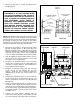
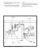
INSTALLATION
NOTE:
All components of the Output Contactor Kit must be
mounted in a clean and dry environment. Maximum
ambient temperature must not exceed 40
o
C outside the
cabinet (55
o
C inside the cabinet).
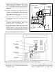
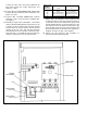
WIRE SIZING NOTE: Care should be taken to see that all
interconnecting wiring is sized and installed in
conformance with the National Electric Code (NEC),
published by the National Fire Protection Association, or
the
Canadian Electrical Code (CEC),
and other applicable
local codes.
Table 1 Complete parts listing.
Description Qty. Part Number
Contactor
Auxiliary Contact (NO)
Connector
Control Transformer
Fuse Block
Fuse
Relay Socket
Relay
Cover
Wire Harness
Wire Harness
Wire Harness
Wire Assembly
Wire Assembly
Wire Assembly
Wire Assembly
Hex Washer Head Screw
ăă(5/16Ć18 x 1/2")
Hex Head Cap Screw
ăă(1/4Ć20 x 3/4")
Flat Washer (1/4")
Lock Washer (1/2")
Hex Head Cap Screw
ăă(1/2Ć13 x 1 1/4")
Flat Washer (1/2")
Lock Washer (1/2")
Taptite
Screw (10Ć32 x
1/2")
Taptite Screw (8Ć32 x 1/2")
Taptite Screw (6Ć32 x 1/2")
Hex Head Cap Screw
ăă(1/4Ć20 x 1 1 /4")
Spacer
TyĆRap
1
1
3
1
1
1
1
1
1
1
1
1
1
1
1
1
4
6
8
8
3
3
3
5
2
2
2
2
10
705310Ć9R
76624ĆX
610290Ć57A
417155ĆS
49454ĆA
64676Ć1P
600434Ć5R
600434Ć6R
705321Ć15R
705337Ć35R
801553Ć34R
801553Ć35R
608809Ć12SA
608809Ć12X
608809Ć12RX
608809Ć12SC
601741Ć73B
601741ĆC
601748Ć1E
601748Ć3J
601741Ć8AB
601748Ć1J
601748Ć3N
601741Ć63C
601741Ć62D
601741Ć61D
601741ĆAB
400684ĆB
69306Ć3D