
User Manual
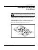


Installing the LonWorks Module in the Drive
3-27
Step 2. Verify That the DC Bus Capacitors are Discharged
Step 2.1 Open the drive’s outer cabinet door.
Step 2.2 Lower the plastic terminal strip shield at the top of the drive.
Step 2.3 Use a voltmeter to verify that there is no voltage at the drive’s AC input
power terminals, R, S, and T.
Step 2.4 Replace the plastic terminal strip shield.
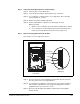
Step 2.5 Ensure that the DC bus capacitors are discharged. To check
DC bus potential:
a. Stand on a non-conductive surface and wear insulated gloves. (600 V)
b. Use a voltmeter to check the DC bus potential at the Voltmeter Test
Points on the Power Module Interface board. See figure 3.14.
Step 3. Remove the Keypad Bracket from the Drive
Refer to figure 3.14 for component locations.
Step 3.1 Record connections to the Regulator board terminal strip if they must be
disconnected to remove the keypad bracket.
Step 3.2 Use a magnetic screwdriver to remove the four screws and lock washers
that fasten the keypad bracket to the hinged mounting panel. Hold the
keypad bracket as you remove the screws.
Step 3.3 Disconnect the Regulator board ribbon cable from the Power Module
Interface board.
Figure 3.14 – LonWorks Module Location in 200 to 400HP @ 460VAC Drives
RE SET
PRO GRAM
REVERSE
FOR W AR D
AUTO
JOG
REMOTE
RUNNING
Password
TOR QUE
Hz
RPM
Kw
AMP S
VOLTS
STO P
START
ENTER
GND
GND
DC–
DC+
DC–
DC+
WT1 WT2
V
RL1
W
WT3
RST
SL2 T
Wiring Tray
DANG ER
U
POWER CONNECT IONS
FULL SHIELD TABS IN AND ROTATE SHIELD OUT
CONNECT USING 360MCM TWO HOLE TERMINAL LUGS
TORQUE TO 32 5IN-LB
LonWorks
Regulator
Board
Keypad
Power Module
Interface Board
Side View
(Enlarged)
Front View