LonWorks Communication Option Module for VTAC 7 Drives M/N 2LW3000 Instruction Manual D2-3498
The information in this manual is subject to change without notice. Throughout this manual, the following notes are used to alert you to safety considerations: ! ATTENTION: Identifies information about practices or circumstances that can lead to personal injury or death, property damage, or economic loss. Important: Identifies information that is critical for successful application and understanding of the product.
CONTENTS Contents Chapter 1 Introduction 1.1 Related Documentation ................................................................................... 1-1 1.2 Getting Assistance from Rockwell Automation ................................................ 1-1 Chapter 2 Getting Started 2.1 Required Equipment........................................................................................ 2-2 2.2 Installation Checklist....................................................................................
Chapter 9 Troubleshooting the LonWorks Module and Network 9.1 Understanding the Status Indicators on the Module ........................................9-1 9.1.1 Module Status LED................................................................................9-2 9.1.2 Service LED...........................................................................................9-2 9.1.3 Wink LED...............................................................................................9-2 9.1.
List of Figures Figure 2.1 – Components of the LonWorks Module ................................................. 2-1 Figure 3.1 – DC Bus Voltage Terminals (1 to 5HP @ 460VAC) .............................. 3-4 Figure 3.2 – LonWorks Module Location in 1 to 5 HP @ 460 VAC Drives .............. 3-5 Figure 3.3 – DC Bus Voltage Terminals (7.5 to 10 HP @ 460 VAC) ....................... 3-8 Figure 3.4 – LonWorks Module Location in 7.5 to 10 HP Drives.............................. 3-9 Figure 3.
IV LonWorks Module for VTAC 7 Drives
List of Tables Table 2.1 – Equipment Shipped with the LonWorks Module .................................... 2-2 Table 2.2 – Required User-Supplied Equipment ...................................................... 2-2 Table 3.1 – Locating the Appropriate Installation Procedure.................................... 3-1 Table 3.2 – Model Numbers for 1 to 5 HP@460 VAC Drives.................................. 3-3 Table 3.3 – Model Numbers for 7.5 to 10 HP @ 460 VAC Drives............................ 3-7 Table 3.
VI LonWorks Module for VTAC 7 Drives
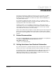
CHAPTER 1 Introduction This manual is intended for qualified electrical personnel responsible for installing, programming, and maintaining AC drives and LonWorks networks. It provides information about the LonWorks Communication Option Module (2LW3000) and using it with VTAC 7 drives. The LonWorks Communication Option module consists of a LonWorks module mounted on an AnyBus board. It is mounted in the VTAC 7 drive and receives its required power from the drive and the network.
1-2 LonWorks Module for VTAC 7 Drives
CHAPTER 2 Getting Started This chapter provides: • A description of the LonWorks module’s components • A list of parts shipped with the module • A list of user-supplied parts required for installing the module • An installation checklist Ribbon Cable Connector Connects the module to the drive. Terminal Block A 5-screw terminal block connects the module to the network. Service Pin A pushbutton identifies the node during installation.
2.1 .Required Equipment Table 2.1 lists the equipment shipped with the LonWorks module. When you unpack the module, verify that the package includes all of these items. Table 2.1 – Equipment Shipped with the LonWorks Module Item Description LonWorks Communications Option module . LonWorks Communication Option Module User Manual (D2-3498) Diskette containing .XIF file Table 2.2 lists user-supplied equipment also required to install and configure the module. Table 2.
2.2 Installation Checklist This section is designed to help experienced users start using the LonWorks module. If you are unsure how to complete a step, refer to the referenced chapter Step Action Refer to ❒ 1 Review the safety precautions for the Throughout module. this manual ❒ 2 Verify that the drive is properly installed. ❒ 4 Install the module in the drive. VTAC 7 AC Drive User Manual (D2-3372) Chapter 3 Verify that the drive and the network are not powered.
2-4 LonWorks Module for VTAC 7 Drives
CHAPTER 3 Installing the LonWorks Module in the Drive The LonWorks module installation procedure differs depending on the drive type. Use table 3.1 to locate the appropriate procedure for your drive. Table 3.1 – Locating the Appropriate Installation Procedure Horsepower Rating Installing the LonWorks Module in the Drive Drive Model Number Use the Procedure in Section … 1 1H21xx 1H22xx 3.3 1 1H41xx 1H42xx 3.1 2 2H21xx 2H22xx 3.3 2 2H41xx 2H42xx 3.1 3 3H21xx 3H22xx 3.3 3 3H41xx 3H42xx 3.
Table 3.1 – Locating the Appropriate Installation Procedure (Continued) Horsepower Rating 3-2 Drive Model Number Use the Procedure in Section … 20 20H41xx 20H42xx 3.5 25 25H41xx 25H42xx 25W21xx 3.5 30 30W21xx 3.4 30 30H41xx 30H42xx 3.5 40 40W21xx 3.4 40 40H41xx 40H42xx 3.5 50 50W21xx 3.4 50 50H41xx 50H42xx 3.5 60 60H41xx 60H42xx 3.5 60 60W21xx 3.4 75 75W21xx 3.4 75 75H41xx 75W41xx 3.4 100 100H21xx 3.4 100 100H41xx 100W41xx 3.4 125 125H41xx 125W41xx 3.
3.1 Installing the Module in 1 to 5 HP@460 VAC Drives ! ATTENTION: Only qualified electrical personnel familiar with the construction and operation of this equipment and the hazards involved should install, adjust, operate, or service this equipment. Read and understand this manual and other applicable manuals in their entirety before proceeding. Failure to observe this precaution could result in severe bodily injury or loss of life.
Step 1. Shut Down the Drive Step 1.1 Disconnect, lock out, and tag all incoming power to the drive. Step 1.2 Wait five minutes for the DC bus capacitors to discharge. Step 1.3 Remove the cover by loosening the four cover screws. Important: Read and understand the warning labels on the inside of the drive before proceeding. Step 2. Verify That the DC Bus Capacitors are Discharged Step 2.1 Use a voltmeter to verify that there is no voltage at the drive’s AC input power terminals (R/L1, S/L2, T/L3). Step 2.
Step 4. Install the LonWorks Module in the Keypad Bracket ! ATTENTION: The drive contains ESD- (Electrostatic Discharge) sensitive parts and assemblies. Static control precautions are required when installing, testing, servicing, or repairing the drive. Erratic machine operation and damage to, or destruction of, equipment can result if this procedure is not followed. Failure to observe this precaution can result in bodily injury. Refer to figure 3.2 for component locations.
Step 4.4 Fasten the LonWorks module to the right side of the keypad bracket using the two metal M3 screws and lock washers for proper grounding. Fasten the left side using the two 6-32 screws and lock washers for proper grounding. Important: You must use the lock washers to properly ground the LonWorks module. Improper grounding of the LonWorks module can result in erratic operation of the drive. Step 5. Reinstall the Keypad Bracket in the Drive Step 5.
3.2 Installing the LonWorks Module in 7.5 to 10 HP @ 460 VAC Drives ! ATTENTION: Only qualified electrical personnel familiar with the construction and operation of this equipment and the hazards involved should install, adjust, operate, or service this equipment. Read and understand this manual and other applicable manuals in their entirety before proceeding. Failure to observe this precaution could result in severe bodily injury or loss of life.
Step 1.3 Remove the cover by loosening the four cover screws. Important: Read and understand the warning labels on the inside of the drive before proceeding. Step 2. Verify That the DC Bus Capacitors are Discharged Step 2.1 Use a voltmeter to verify that there is no voltage at the drive’s AC input power terminals (R/L1, S/L2, T/L3). Step 2.2 Ensure that the DC bus capacitors are discharged. To check DC bus potential: a. Stand on a non-conductive surface and wear insulated gloves. b.
Step 4. Install the LonWorks Module in the Keypad Bracket ! ATTENTION: The drive contains ESD- (Electrostatic Discharge) sensitive parts and assemblies. Static control precautions are required when installing, testing, servicing, or repairing the drive. Erratic machine operation and damage to, or destruction of, equipment can result if this procedure is not followed. Failure to observe this precaution can result in bodily injury. Refer to figure 3.4 for component locations.
Step 4.3 Align the LonWorks module on the four mounting tabs on the keypad bracket. Make sure that the ribbon cable is not pinched between the keypad bracket and the LonWorks module. Step 4.4 Fasten the LonWorks module to the right side of the keypad bracket using the two metal M3 screws and lock washers for proper grounding. Fasten the left side using the two 6-32 screws and lock washers for proper grounding. Important: You must use the lock washers to properly ground the LonWorks module.
3.3 Installing the LonWorks Module in 1 to 20 HP@230 VAC Drives ! ATTENTION: Only qualified electrical personnel familiar with the construction and operation of this equipment and the hazards involved should install, adjust, operate, or service this equipment. Read and understand this manual and other applicable manuals in their entirety before proceeding. Failure to observe this precaution could result in severe bodily injury or loss of life.
If the drive is panel-mounted, this procedure will be easier to perform if the drive is removed from the panel. Unless otherwise indicated, keep all hardware that is removed. You will need it for reassembly. This includes screws, lock washers, and rivets. Important: Read and understand the warning labels on the outside of the drive before proceeding. Step 1. Shut Down the Drive Step 1.1 Disconnect, lock out, and tag all incoming power to the drive. Step 1.
Step 3.3 Spread the retaining clips on the Regulator board ribbon cable (on the right side) to disconnect it from the Base Board. Step 3.4 Remove the keypad bracket. Place it with the keypad down on a flat surface. If you cannot lay it flat, tie it up to prevent damage to wiring. Step 4. Install the LonWorks Module in the Keypad Bracket Refer to figure 3.6 for component locations. Step 4.1 Remove the LonWorks module from its anti-static wrapper.
Keypad Bracket Regulator Board Terminal Strip Power Terminal Strip Figure 3.6 – 1 to 20 HP @ 230 Volt Drive Step 5.5 Reinstall the cover. Align all cover screws into the heat sink before tightening any of them. To maintain the integrity of NEMA 4X/12 drives, sequentially tighten the cover screws to ensure even compression of the gaskets. Do not exceed 2.2 Nm (20 in-lb) of torque on these screws.
3.4 Installing the LonWorks Module in 30 to 100HP@230VAC and 75 to 200 @ 460VAC Drives ! ATTENTION: Only qualified electrical personnel familiar with the construction and operation of this equipment and the hazards involved should install, adjust, operate, or service this equipment. Read and understand this manual and other applicable manuals in their entirety before proceeding. Failure to observe this precaution could result in severe bodily injury or loss of life.
Step 1. Shut Down the Drive Step 1.1Disconnect, lock out, and tag all incoming power to the drive. Step 1.2 Wait five minutes for the DC bus capacitors to discharge. Step 1.3 Open the drive’s outer cabinet door. Step 1.1 Read and understand the warning labels on the inside of the drive before proceeding. Step 2. Verify That the DC Bus Capacitors are Discharged Step 2.1 Use a voltmeter to verify that there is no voltage at the drive’s AC input power terminals (R/L1, S/L2, T/L3 or U/T1, V/T2, W/T3).
Step 3. Remove the Keypad Bracket from the Drive Step 3.1 Remove the Power Module from the drive cabinet. Step 3.2 If the drive has: • A Regulator board and terminal cover: Remove the three M4 screws from the cover plate over the Regulator board. Remove the cover. See figure 3.8. • A terminal cover only: If you have this type of drive, this procedure is easier to perform if you lay the drive on its side. Remove the side cover from the drive.
Step 4. Install the LonWorks Module in the Keypad Bracket ! ATTENTION: The drive contains ESD- (Electrostatic Discharge) sensitive parts and assemblies. Static control precautions are required when installing, testing, servicing, or repairing the drive. Erratic machine operation and damage to, or destruction of, equipment can result if this procedure is not followed. Failure to observe this precaution can result in bodily injury. Refer to figures 3.8 and 3.9 for component locations. Step 4.
Regulator Board Front Ribbon Cable Connecting Regulator Board and Base Board Top View Ribbon Cable Connecting Regulator Board and LonWorks Module LonWorks Back Side of Regulator Board Metal Screw To Base Board Insulator Ribbon Cable Connector to Connect Base Board Ribbon Cable Connector to Connect LonWorks Module Ribbon Cable Connector to Connect Keypad Rear View of Regulator Board Plastic Rivet Terminal Strip Figure 3.
3.5 Installing the LonWorks Module in 15 to 25 HP and 25 to 60 HP @ 460VAC Drives ! ATTENTION: Only qualified electrical personnel familiar with the construction and operation of this equipment and the hazards involved should install, adjust, operate, or service this equipment. Read and understand this manual and other applicable manuals in their entirety before proceeding. Failure to observe this precaution could result in severe bodily injury or loss of life.
Important: Read and understand the warning labels on the outside of the drive before proceeding. Step 1. Shut Down the Drive Step 1.1 Disconnect, lock out, and tag all incoming power to the drive. Step 1.2 Wait five minutes for the DC bus capacitors to discharge. Step 1.3 Remove the cover by loosening the four cover screws. Important: Read and understand the warning labels on the inside of the drive before proceeding. Step 2. Verify That the DC Bus Capacitors are Discharged Step 2.
DC Bus Volts Input Wiring Figure 3.11 – DC Bus Voltage Terminals (25 to 60 HP @ 460 VAC) Step 3. Remove the Keypad Bracket from the Drive See figure 3.12 (15 to 25 HP @ 460 VAC) or 3.13 (25 to 60 HP @ 460 VAC) for part locations. Step 3.1 Record connections to the Regulator board terminal strip if they must be disconnected to remove the keypad bracket. Step 3.2 Loosen the thumb screw on the left side of the keypad bracket.
Step 4. Install the LonWorks Module in the Keypad Bracket ! ATTENTION: The drive contains ESD- (Electrostatic Discharge) sensitive parts and assemblies. Static control precautions are required when installing, testing, servicing, or repairing the drive. Erratic machine operation and damage to, or destruction of, equipment can result if this procedure is not followed. Failure to observe this precaution can result in bodily injury. Step 4.1 Remove the LonWorks module from its anti-static wrapper.
Regulator Board Front View LonWorks Module Top View Figure 3.13 – LonWorks Module Location in 25 to 60 HP @ 460 VAC Drives Step 4.2 Align the LonWorks module on the four mounting tabs on the keypad bracket. Make sure that the ribbon cable is not pinched between the keypad bracket and the LonWorks module. Step 4.3 Fasten the LonWorks module to the right side of the keypad bracket using the two metal M3 screws and lock washers for proper grounding.
To maintain the integrity of NEMA 4X/12 drives, sequentially tighten the cover screws to ensure even compression of the gaskets. Do not exceed 2.2 Nm (20 in-lb) of torque on these screws.
3.6 Installing the LonWorks Module in 200 to 400 HP @ 460 VAC Drives ! ATTENTION: Only qualified electrical personnel familiar with the construction and operation of this equipment and the hazards involved should install, adjust, operate, or service this equipment. Read and understand this manual and other applicable manuals in their entirety before proceeding. Failure to observe this precaution could result in severe bodily injury or loss of life.
Step 2. Verify That the DC Bus Capacitors are Discharged Step 2.1 Open the drive’s outer cabinet door. Step 2.2 Lower the plastic terminal strip shield at the top of the drive. Step 2.3 Use a voltmeter to verify that there is no voltage at the drive’s AC input power terminals, R, S, and T. Step 2.4 Replace the plastic terminal strip shield. Step 2.5 Ensure that the DC bus capacitors are discharged. To check DC bus potential: a. Stand on a non-conductive surface and wear insulated gloves. (600 V) b.
Step 4. Install the LonWorks Module ! ATTENTION: The drive contains ESD- (Electrostatic Discharge) sensitive parts and assemblies. Static control precautions are required when installing, testing, servicing, or repairing the drive. Erratic machine operation and damage to, or destruction of, equipment can result if this procedure is not followed. Failure to observe this precaution can result in bodily injury. Step 4.1 Remove the LonWorks module from its anti-static wrapper.
CHAPTER 4 Connecting the Drive to the Network and Applying Power ATTENTION: The drive may contain high voltages that can cause injury or death. Remove all power from the drive, then verify power has been removed before installing or removing a LonWorks module. Failure to observe these precautions could result in severe bodily injury or loss of life. ! 4.
4.3 Applying Power ! ATTENTION: Unpredictable operation may occur if parameter settings and switch settings are not compatible with your application. Verify that setting are compatible with your application before applying power to the drive. Failure to observe these precautions could result in severe bodily injury or loss of life. Step 1. Close the drive cover or re-install the cover on the drive. Step 2. Apply power to the drive. The module receives its power from the connected drive.
CHAPTER 5 Installing the Drive as a Node in the Network ! ATTENTION: This procedure requires power be applied to the drive and the network while the cover is off of the drive. The user is responsible for ensuring safe conditions for operating personnel. Failure to observe this precaution could result in severe bodily injury or loss of life. The module is installed as a node in the LonWorks network using a standard LonWorks installation tool such as LonMaker for Windows.
5-2 LonWorks Module for VTAC 7 Drives
CHAPTER 6 Programming the Drive for Network Communication This section describes how to configure a VTAC 7 drive for use with an LonWorks network. The sections that follow describe the VTAC 7 parameters related to LonWorks network operation. For other drive parameter descriptions, refer to the VTAC 7 User Manual. 6.1 Setting the Control Source (P.
6.2 Setting the Network Connection Type (P.061) Parameter Range: 0 = Basic drive connection 1 = Full drive connection Default Setting: 0 Parameter Type: Configurable Refer also to parameters: N/A Parameter P.061 (Network Connection Type) selects the type of network connection. Setting P.061 = 1 provides full drive control from the network. Any drive data that has been assigned a network register is transferred over the network. Parameter P.
P.062 Option Port: Communication Loss Response (continued) If P.062 = 0 The drive will consider a loss of network communication to be a drive fault, resulting in an IET-type stop sequence. When P.062 is set to IET fault (0) and communication is lost: • The drive latches a fault condition and performs a coast stop. • The network communication loss fault is generated (nCL is displayed). • The front panel REMOTE LED blinks, indicating that the network is inactive.
P.062 Option Port: Communication Loss Response (continued) If P.062 = 2 The drive gets its speed/torque reference from the terminal strip analog input and its stop input from the terminal strip stop input. All other inputs are held at the last values received from the network. This allows the network to continue controlling the drive reference with a direct-wired analog output to input, and to stop the drive with a direct-wired digital output to input. Note that if P.
6.4 Setting the Speed Display Scale (P.028) Parameter Range: 10 to 9999 Default Setting: Synchronous speed based on H.001 (assuming a 4-pole motor) Parameter Type: Tunable Parameter P.028 (Speed Display Scaling) defines the scaling value applied to the manual reference, the selected speed reference, and the output speed displays. P.028 must be set to 100 for nvoDriveSpeed to show the correct percent of nominal speed. This value is written by the LonWorks board at start up.
6-6 LonWorks Module for VTAC 7 Drives
CHAPTER 7 Operating the Drive Using a LonMark Profile A LonMark profile defines the functional profile for a node communicating with other nodes. The profile specifies which SNVTs (Standard Network Variable Types) and SCPTs (Standard Configuration Property Types) are used, and provides a semantic meaning about the information being communicated. When a profile is implemented in a node, it’s called a LonMark object. One node can have several objects implemented.
Variable Speed Motor Drive: 6010 nv1 nv2 nviDrvSpee dStpt SNVT_switch nviDrvSpe edScale SNVT_ lev_percent Mandatory Network Variables Optional Network Variables n v5 nvoDrvSpe ed SNVT _lev_percent nv6 nvoDrvCurnt SNVT_amp nv7 nvoDrvVolt SNVT _volt nv8 nvoDrvPwr SNVT _power_kilo nv9 nvoDrvRunHo urs SNVT _time_hour Configura tion P ro perties nc1 7 - nciLocation (op tional) nc50 - nciMa xSp eed (ma ndatory) nc53 - nciMinSpeed (m anda tory) nc48 - nciRcvHrtB t (optio nal) nc49 - nciSnd HrtBt (m
7.1 Input Network Variables (NVIs) Section 7.1 describes the input network variables (NVIs). Node Object Request Definition: network input SNVT_obj_request nviObjRequest; Explanation: Enables control commands and updates from the network. The status of the node is reported in nvoObjStatus (see section 7.2). Range: • RQ_NORMAL is the normal request mode when node is in normal run mode. • RQ_DISABLED will stop the motor.
Drive Speed Setpoint Definition: network input SNVT_switch nviDrvSpeedStpt. Explanation: Provides a low-resolution speed setpoint. When nviDrvSpeedStpt.State is set to zero, the drive stops based on the stop mode defined by drive parameter P.025. Important: Requested speed will not be greater than the value defined by nciMaxSpeed or less than the value defined by nciMinSpeed Range: State 0 1 1 1 0xFF Percent Value N/A 0% 0.5% to 100.0% 100.0% N/A Requested Speed Stopped 0% 0.5 to 100.0% 100.
Run/Jog Select Definition: network input SNVT_switch nviJogSel Explanation: Selects run mode or jog mode for the drive. • Jog reference frequency is defined by nciJogRef. • Start/stop jogging the drive with nviSpeedStpt.state. • For reverse operation, set (nviSpeedScale * nviSpeedStpt.value) negative Range: 0 = Run Mode 1 = Jog Mode . OCL Enable Definition: network input config SNVT_switch nviOCL_enable Explanation: Enables the Outer Control Loop (OCL).
7.2 Output Network Variables (NVO) Section 7.2 describes the output network variables (NVOs). Node Object Status Definition: network output SNVT_obj_status nvoObjStatus Explanation: Reports node object status. It is updated every time there is a status change. See Node Object Request in section 7.1. Range: Status Reported Definition Invalid_request The node has been asked for an unsupported request. Report_mask Report supported fields.
Drive Current Definition: network output SNVT_amp nvoDrvCrnt Explanation: Provides the drive output current in amps. Drive Speed Definition: network output SNVT_level_percent nvoDrvSpeed Explanation: Provides the speed of the drive as a percentage of the nominal speed. Since nominal speed and nominal frequency are tightly connected, the output value is calculated on the nominal (base) frequency and the running (output) frequency.
Fault Word 1 Definition: network output SNVT_state nvoFault1 Explanation: Range: Bit 0 1 2 3 4 5 6 7 8 9 10 11 12 13 14 15 Description Overcurrent steady state Overcurrent while accelerating Overcurrent while decelerating Overcurrent during DC braking DC bus too high DC bus too low Electronic thermal overload Thermostat overtemperature Function loss EPROM defaults restored Loss of communication from serial port Spurious UART interrupt Torque/current self-tuning fault Overspeed (10% over max speed) Outpu
Parameter Value Out 7.3 Definition: network output SNVT_count nvoParam Explanation: Used as feedback variable for generic parameter requests. See nciParRdAddress (section 7.3). Configuration Properties (NCIs) This section describes the configuration properties (NCIs).
Minimum Send Time Definition: network input config SNVT_time_sec nciMinOutTim; Explanation: Selects the minimum period of time that expires before the network output variables can be resent. This is good for limiting use of bandwidth on the LonWorks channel. NciMinOutTm parameter overrides nciSndHrtBt. Range: 0.0 (Disabled) to 6,5553.4 seconds Default: 0.
Minimum Speed Definition: network input config SNVT_lev_percent nciMinSpeed Explanation: Defines the minimum speed of a motor (around zero). Its value is entered as a percent of nominal frequency, as defined by the nominal frequency (nciNmlFreq) configuration value. Set this parameter when the drive is stopped. NciMinSpeed will be in effect on the next frequency setting. If nciNmlFreq = 50 Hz and nciMinSpeed = 10%, the minimum frequency is 5 Hz. -163.84 ≤minimum speed ≤maximum speed ≤163.
Current Limit Definition: network input config SNVT_lev_percent nciCurLimit Explanation: Sets the current limit in percent of motor nameplate amps. Default: Read from drive Generic Parameter Register Setting, Write Definition: network input config SNVT_count nciParWriAddress Explanation: Selects register to write to in the drive. The first digit is the drive drop number. The remaining digital represent the register. For example, 203 = drop 2, register 3. See section 8.
Generic Parameter Register Setting, Read Definition: network input config SNVT_count nciParRdAddress; Explanation: Selects register in the drive to read. The first digit is the drive drop number. The remaining digital represent the register. For example, 203 = drop 2, register 3. See section 8.6 for more information.
7-14 LonWorks Module for VTAC 7 Drives
CHAPTER 8 Conditions Required for Operation This chapter describes the conditions required for performing some common actions and how the combination of SNVTs and SCPTs affect the operation of the drive. 8.1 General Guidelines • The LonWorks module and the drive must be installed and configured correctly. Note the following VTAC 7 parameter settings: • P.061 = 1. This enables the LonWorks module to have full access to all parameters in the drive.
8.3 Stopping the Drive The drive will stop using the stop mode selected in parameter P.025 if any of the following conditions are met: • NviSpeedStpt.state is set to any value but 1 • The node is brought offline • RQ_DISABLED is requested in nviObjRequest 8.4 Setting the Frequency The actual value written to the LonWorks module = (nviDrvSpeedStpt*0.5*nviDrvSpeedScale*0.005*nciNmlFreq*100) / (100*100) Notes for above equation: • Multiplied by 0.005 and 0.
NciWriAddr Address NciWriAddr nciWriValue nviObjRequest Result 159 Drop 1 Reg59 159 0 X Network Inertia Comp Reg Enable is set to 0. 157 Drop 1 Reg57(C) 157 0 Not RQ_PROGRAM For example: RQ_NORMAL Trim Ref Source is set to 0 but not read in by drive. (Configurable parameter) X X X X RQ_PROGRAM All tunable parameters read in by drive. All configurable parameters read if drive is stopped. If (nciWriAddr > X63) = X63 X63 X63 X RQ_PROGRAM Address written to with X.
8-4 LonWorks Module for VTAC 7 Drives
CHAPTER 9 Troubleshooting the LonWorks Module and Network ATTENTION: Checking the status indicators on the LonWorks module requires power be applied to the drive and the network while the cover is off of the drive. The user is responsible for ensuring safe conditions for operating personnel. Failure to observe this precaution could result in severe bodily injury or loss of life. ! This chapter contains information for troubleshooting the LonWorks module and network. 9.
9.1.1 Module Status LED Table 9.1 – Module Status LED: State Definitions LED State Cause Corrective Action Solid green Normal operation/power on None required. Flashing green Initialization of AnyBus/VTAC 7 interface None required. Flashing red Recoverable fault: • 4 Hz: • 4 Hz: Check that P.061 is set to 1 for full access to all drops. • 2 Hz: Heartbeat timeout • Solid red received. 1 Hz: Node is offline. Unrecoverable fault (hardware error). • 2 Hz: • 1 Hz: Replace module. 9.1.
9.1.4 Communication Module Status LED Table 9.4 – Communication Module Status LED: State Definitions LED State Solid green 9.2 Cause The module has been initiated correctly and is functioning properly. Corrective Action None required. Flashing red Software error. Restart the module. Solid red Cycle power to the drive and module. If cycling power does not correct the problem, replace the module. A hardware error has occurred.
Error LonWorks Module LED 1 RAM error Three red flashes, then constant red. The software has detected a RAM checksum error and has not started the application and never will. Unrecoverable fault. Try restart. Flash error. Six red flashes, then constant red. The software has detected a Flash checksum error and has not started the applicaiton and never will. Unrecoverable fault. The software has been damaged. Hardware error. Red. Software application was not started. Unrecoverable fault.
APPENDIX A Technical Specifications Communications Network Protocol LonWorks Data Rates 78 kbps Maximum bus length 2000 m Maximum node-to-node distance 500 m Electrical Consumption 300 mA on the +5 power connection (+/-5%) Mechanical Dimensions Height 18 mm Length 172 mm Width 99 mm Weight Environmental Temperature Operating - 10 to 50 C (14 to 149 F) Storage -40 to 85 C (-40 to 185 F) Relative humidity 5 to 95% non-condensing Regulatory Compliance Technical Specifications UL 508C a
A-2 LonWorks Module for VTAC 7 Drives
INDEX Numerics 1 to 20 HP @ 230 VAC drive installation, 3-11 1 to 5 HP @ 460 VAC drive installation, 3-3 15 to 25 HP @ 460 VAC drive installation, 3-20 200 to 400 HP @ 460 VAC drive installation, 3-26 25 to 60 HP @ 460 VAC drive installation, 3-20 30 to 100 HP @ 230 VAC drive installation, 3-15 7.5 to 10 HP @ 460 VAC drive installation, 3-7 75 to 200 @ 460 VAC drive installation, 3-15 B 30 to 100 HP @ 230 VAC drives, 3-15 7.
Index-2 LonWorks Module for VTAC 7 Drives
U.S. Drives Technical Support Tel: (1) 262.512.8176, Fax: (1) 262.512.2222, Email: support@drives.ra.rockwell.com, Online: www.ab.com/support/abdrives Publication D2-3498– 2001 Copyright © 2001 Rockwell Automation, Inc. All Rights Reserved. Printed in USA.