
User Manual Owner's manual

44 Rockwell Automation Publication 290D-UM001A-EN-P - June 2012
Chapter 2 Installation and Wiring
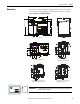
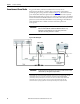
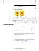
Figure 15 - Gland Connection
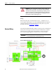
Wiring Terminal Detail
The power, control, and ground wire capacity and the tightening torque
requirements are shown in Ta b l e 8
. The maximum number of connections
per terminal are shown in Ta b le 7
. As shown in Figure 16 all the terminals are
found in the wiring area. Access can be gained by removing the terminal access
cover plate.
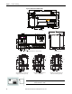
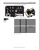
Conduit Entry (Standard)
External PE
connection
Inputs/Outputs
Network
Optional ArmorConnect Quick
Disconnect Feature
Three-Phase
Power
Receptacle
Motor
Receptacle
Control Power
Receptacle
Gland Plate