
User Manual Owner's manual

30 Rockwell Automation Publication 290D-UM001A-EN-P - June 2012
Chapter 1 Product Overview
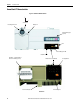
Status LEDs and Reset
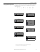
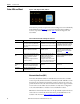
Figure 7 - Status, Diagnostic LEDs, and Reset
ArmorStart LT provides comprehensive status and diagnostics via 12 individually
marked LEDs shown in Figure 7
, located on the ECM module. In addition, a
local reset is provide for clearing of faults. Ta b le 4
details the diagnostic and
status LEDs.
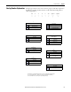
Electronic Data Sheet (EDS)
ArmorStart LT EtherNet/IP has an embedded electronic data sheet. An EDS
consists of specially formatted text files, as defined by the CIP™. EDS files contain
details about the readable and configurable parameters of the device. They also
provide information about the I/O connections that the device supports and the
content of the associated data structures. EDS are used by device configuration
tools, such as RSNetWorx™, and data servers such as RSLinx® Classic.
EDS files for all ArmorStart LT devices can be uploaded directly from the device
via the web server interface. Rockwell Automation product EDS files are also
available on the internet at: http://www.ab.com/networks/eds
.
Table 4 - ArmorStart LT Status and Diagnostics Indicators
Indicator Description Color_1 Color_2
PWR LED The bicolor (green/yellow) LED shows the
state of the control voltage. When LED is
off, switched and/or unswitched power is
not present.
Solid green is illuminated when switched
and unswitched control power is within its
specified limits and has the proper polarity.
Solid yellow is illuminated when switched
or unswitched control power is outside its
specified limits or has incorrect polarity.
RUN/FLT LED The bicolor (green/red) LED combines the
functions of the Run and Fault LEDs.
Solid green is illuminated when a Run
command is present.
The LED will blink red in a prescribed fault
pattern when a protection fault (trip)
condition is present. See Tab le 5 for fault
blink patterns.
NET – Network Status
LED
The bicolor (green/red) LED indicates the
status of the CIP network connection. See
Network Status Indicator for further
information.
Flashing bicolor (red/green) indicates a
self-test on power up.
Flashing green indicates an IP address is
configured, no CIP connections are
established, and an Exclusive Owner
connection has not timed out.
Steady green indicates at least one CIP
connection is established and an Exclusive
Owner connection has not timed out.
Flashing red indicates the connection has
timed out. Steady Red indicates a duplicate
IP Address detected.
I/O Status
Enunciators 0…5
LEDs
Six yellow LEDs are numbered 0…5 and
indicate the status of the input/output
connectors. One LED for each I/O point.
Yellow is illuminated when input is valid or
output is on.
Off when input is not valid or the output is
not turned on.
Reset Button The blue reset button will cause a
protection fault reset to occur.
——