
User Manual Owner's manual


Rockwell Automation Publication 290D-UM001A-EN-P - June 2012 167
Chapter 5
Diagnostics
Overview
This chapter describes the fault diagnostics of the ArmorStart LT Distributed
Motor Controller and the conditions that cause various faults to occur.
Status LEDs and Reset
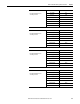
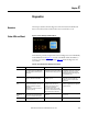
Figure 39 - Status and Diagnostic LEDs and Reset
ArmorStart LT provides comprehensive status and diagnostics via 12 individually
marked LEDs shown in Figure 39
, located on the ECM module. In addition, a
local reset is provide for clearing of faults. Ta b le 22
details the diagnostic and
status LEDs.
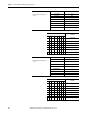
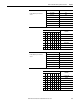
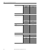
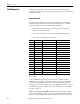
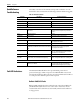
Table 22 - ArmorStart LT Status and Diagnostics Indicators
Indicator Description Color_1 Color_2
PWR LED The bicolor (green/yellow) LED shows the
state of the control voltage. When LED is
off, switched and/or unswitched power is
not present.
Solid green is illuminated when switched
and unswitched control power is within its
specified limits and has the proper polarity.
Solid yellow is illuminated when switched
or unswitched control power is outside its
specified limits or has incorrect polarity.
Flashing yellow indicates line voltage is not
present (294 units only).
RUN/FLT LED The bicolor (green/red) LED combines the
functions of the Run and Fault LEDs.
Solid green is illuminated when a Run
command is present.
The LED will blink red in a prescribed fault
pattern when a protection fault (trip)
condition is present. See table for fault
blink patterns.
NET – Network Status
LED
The bicolor (green/red) LED indicates the
status of the CIP network connection. See
Network Status Indicator for further
information.
Flashing bicolor (red/green) indicates a
self-test on power up.
Flashing green indicates a node address is
configured, no CIP connections are
established, and an Exclusive Owner
connection has not timed out.
Steady green indicates at least one CIP
connection is established and an Exclusive
Owner connection has not timed out.
Flashing red indicates the connection has
timed out. Steady Red indicates a duplicate
IP Address detected.
I/O Status
Enunciators 0…5
LEDs
Six yellow LEDs are numbered 0…5 and
indicate the status of the input/output
connectors. One LED for each I/O point.
Yellow is illuminated when input is valid or
output is on.
Off when input is not valid or the output is
not turned on.
Reset Button The blue reset button will cause a
protection fault reset to occur.
——