User Manual ArmorStart® LT Distributed Motor Controller Catalog Numbers 290D, 291D, 294D
Important User Information Because of the variety of uses for the products described in this publication, those responsible for the application and use of this control equipment must satisfy themselves that all necessary steps have been taken to assure that each application and use meets all performance and safety requirements, including any applicable laws, regulations, codes and standards.
General Precautions In addition to the precautions listed throughout this manual, the following statements, which are general to the system, must be read and understood. ATTENTION: This manual is intended for qualified service personnel responsible for setting up and servicing these devices. The user must have previous experience with and a basic understanding of electrical terminology, configuration procedures, required equipment, and safety precautions.
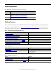
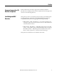
Software Requirements The table lists the versions of software that are required. Software Version RSLinx Classic 2.56 or later RSLogix 5000 17.01 or later Download the most current version of the Add-On Profile from http://www.rockwellautomation.com/support/downloads.html. RSNetworx 11 or later Additional Resources These documents and websites contain additional information concerning related Rockwell Automation products. You can view or download publications at http:/www.rockwellautomation.
Rockwell Automation Support Rockwell Automation provides technical information on the Web to assist you in using its products. At http://www.rockwellautomation.com/support/, you can find technical manuals, a knowledge base of FAQs, technical and application notes, sample code and links to software service packs, and a MySupport feature that you can customize to make the best use of these tools.
Notes: 6 Rockwell Automation Publication 290D-UM001A-EN-P - June 2012
Summary of Changes New and Updated Information This table contains the changes made to this revision.
Summary of Changes Notes: 8 Rockwell Automation Publication 290D-UM001A-EN-P - June 2012
Preface European Communities (EC) Directive Compliance If this product has the CE mark it is approved for installation within the European Union and European Economic Area (EEA). It has been designed and tested to meet the following directives.
Preface Introduction 10 The ArmorStart LT is an integrated, pre-engineered, motor starting solution designed for use in material handling applications. ArmorStart LT is the latest addition to the ArmorStart portfolio. ArmorStart LT is a leader in the market place given its compact size and high performance features in network, I/O, and motor control. This manual will guide you through the features and functionality when installing the product.
Table of Contents Important User Information . . . . . . . . . . . . . . . . . . . . . . . . . . . . . . . . . . . . . . . 2 General Precautions . . . . . . . . . . . . . . . . . . . . . . . . . . . . . . . . . . . . . . . . . . . . . . . . 3 Software Requirements . . . . . . . . . . . . . . . . . . . . . . . . . . . . . . . . . . . . . . . . . . . . . 4 Additional Resources . . . . . . . . . . . . . . . . . . . . . . . . . . . . . . . . . . . . . . . . . . . . . . . 4 Rockwell Automation Support . . . . .
Table of Contents Optional HOA Selector Keypad with Jog Function(Bulletin 294D only) . . . . . . . . . . . . . . . . . . . . . . . . . . . . . 36 Keypad Local Control . . . . . . . . . . . . . . . . . . . . . . . . . . . . . . . . . . . . . . . . . 36 Keypad and HOA Disable Parameter. . . . . . . . . . . . . . . . . . . . . . . . . . . . 37 Source Brake Contactor and Connector (Bulletin 294D only) . . . . . . . .37 Chapter 2 Installation and Wiring 12 Receiving . . . . . . . . . . . . . . . . . . . . .
Table of Contents Recommended Cord Grips . . . . . . . . . . . . . . . . . . . . . . . . . . . . . . . . . . . . .61 Shield Terminating Connectors . . . . . . . . . . . . . . . . . . . . . . . . . . . . . . . . 61 Electromagnetic Compatibility (EMC) . . . . . . . . . . . . . . . . . . . . . . . . . . . . . 62 General Notes (Bulletin 294D only) . . . . . . . . . . . . . . . . . . . . . . . . . . . .62 Ethernet, DeviceNet, and I/O Connections . . . . . . . . . . . . . . . . . . . . . . . . .
Table of Contents Chapter 5 Diagnostics Overview . . . . . . . . . . . . . . . . . . . . . . . . . . . . . . . . . . . . . . . . . . . . . . . . . . . . . . . .167 Status LEDs and Reset . . . . . . . . . . . . . . . . . . . . . . . . . . . . . . . . . . . . . . . . . . . .167 Fault Diagnostics. . . . . . . . . . . . . . . . . . . . . . . . . . . . . . . . . . . . . . . . . . . . . . . . .168 Protection Faults . . . . . . . . . . . . . . . . . . . . . . . . . . . . . . . . . . . . . . . . . . . . .
Table of Contents CLASS CODE 0x0005 . . . . . . . . . . . . . . . . . . . . . . . . . . . . . . . . . . . . . . .216 Discrete Input Point Object. . . . . . . . . . . . . . . . . . . . . . . . . . . . . . . . . . . . . . .219 CLASS CODE 0x0008 . . . . . . . . . . . . . . . . . . . . . . . . . . . . . . . . . . . . . . .219 Discrete Output Point Object . . . . . . . . . . . . . . . . . . . . . . . . . . . . . . . . . . . . .220 CLASS CODE 0x0009 . . . . . . . . . . . . . . . . . . . . . . . . . . . . . . . .
Table of Contents Notes: 16 Rockwell Automation Publication 290D-UM001A-EN-P - June 2012
Chapter 1 Product Overview Bulletin Network Communications: EtherNet/IP DeviceNet Horsepower Range: 0.5…5 Hp (0.37…3.3 kW) 0.5…2 Hp (0.37…1.
Chapter 1 Product Overview Description ArmorStart LT is available with Full Voltage, Full Voltage Reversing, or Variable Speed motor control performance. It comes equipped with a UL Listed At-motor disconnect that supports a lock-out tag-out (LOTO) provision. ArmorStart LT is listed as suitable for group installations per UL and can be applied with either branch circuit breaker protection or fuse protection.
Product Overview Features Chapter 1 The ArmorStart LT provides many features and benefits that are unsurpassed in the market place: • Robust IP66, UL Type 4/12 enclosure • UL Listed, Suitable for Group Motor Applications • UL Listed, At-motor disconnect switch • Native support for DeviceNet • 6 user configurable I/O points • DeviceLogix • Zone interlock protocol (ZIP) • Optional internal power supply • Optional electromechanical brake contactor • Optional local control via Hand-Off-Auto keypad • Optional
Chapter 1 Product Overview Feature Description Standard Features Across Product Family UL Listed “Suitable for Group Motor Applications” — Where NFPA 70 (NEC) or 79 are required installation standards, this Listing allows two or more motors to be connected to the same branch circuit without individual motor branch short circuit or ground fault protection. Refer to Appendix A for details.
Product Overview Chapter 1 disconnect shielded motor cable contact your local sales representative for details. Local and remote status and diagnostics — ArmorStart LT offers comprehensive status and diagnostics for I/O, Network, and device health via 12 LEDs found on the electronic control module (ECM). If a fault occurs a local fault reset button allows the user to quickly get the process started after corrective action is taken.
Chapter 1 Product Overview ArmorStart LT Characteristics Figure 1 - Bulletin 290D/291D ArmorStart LT 0 Off HOA Keypad (optional) 1 On IP Address Switches On/Off Switch Status and Diagnostic LEDs LockOut/TagOut Provision Reset Wiring Access ECM (Electronic Control Module) 6 Configurable I/Os Gland Plate – Conduit/Cord Grip or ArmorConnect® Media (optional) DeviceNet Connector Protective Earth (PE) 22 Rockwell Automation Publication 290D-UM001A-EN-P - June 2012
Product Overview Catalog Number Explanation Chapter 1 Examples given in this section are for reference purposes. This basic explanation should not be used for product selection; not all combinations will produce a valid catalog number.
Chapter 1 Product Overview ArmorStart LT Characteristics Figure 2 - Bulletin 294D ArmorStart LT 0 Off 1 On On/Off Switch Wiring Access LockOut/TagOut Provision Hand-Off-Auto Keypad (optional) Reset Status and Diagnostic LEDs IP Address Switches Gland Plate – Conduit/Cord Grip or ArmorConnect Media (optional) ECM (Electronic Control Module) Protective Earth (PE) DeviceNet connector Bottom View 24 Rockwell Automation Publication 290D-UM001A-EN-P - June 2012 6 Configurable I/Os
Product Overview Catalog Number Explanation Chapter 1 Examples given in this section are for reference purposes. This basic explanation should not be used for product selection; not all combinations will produce a valid catalog number.
Chapter 1 Product Overview Basic Operation Group Motor Installations for USA and Canada Markets The ArmorStart LT Distributed Motor controllers are listed for use with each other in group installations per NFPA 79, Electrical Standard for Industrial Machinery and NFPA 70, the National Electrical Code. When applied according to the group motor installation requirements, two or more motors are permitted on a single branch circuit.
Product Overview Chapter 1 Figure 4 - Control Circuit Wiring Diagram — Multiple External Power Supplies ArmorStart LT L1 L2 L3 Switched Control Power Off * Unswitched Control Power Disconnect EtherNet Comms Inputs Motor Control Outputs Motor Controller A1 T1 T2 A2 A3 T3 * Control power output is determined by disconnect status Class 2 External Switched 24VDC Power Supply Class 2 External Unswitched 24VDC Power Supply L + 24VDC - N L + 24VDC - N Figure 5 - Control Circuit Wiring
Chapter 1 Product Overview Motor Circuit The ArmorStart LT Distributed Motor Controllers are rated to operate the following types of three-phase squirrel-cage induction motors: Bulletin 290D/291D: 0.5 Hp (0.37 kW) to 5 Hp (3 kW) @ 480/277V AC Bulletin 294D: 0.5 Hp (0.37 kW) to 2 Hp (1.5 kW) @ 480/277V AC Local I/O The ArmorStart LT provides as standard, 6 user configurable I/O points. By default, all points are configured as an Input.
Product Overview Chapter 1 Figure 6 - Full-Voltage Start 100% Percent Voltage Time (seconds) Mode of Operation Bulletin 294D Sensorless Vector Performance Using a distributed AC drive to operate mechanical equipment at optimum speed helps reduce energy costs and eliminates mechanical wear and tear that can occur in the mechanical parts.
Chapter 1 Product Overview Status LEDs and Reset Figure 7 - Status, Diagnostic LEDs, and Reset ArmorStart LT provides comprehensive status and diagnostics via 12 individually marked LEDs shown in Figure 7, located on the ECM module. In addition, a local reset is provide for clearing of faults. Table 4 details the diagnostic and status LEDs.
Product Overview Fault Diagnostics Chapter 1 Fault diagnostics capabilities built in the ArmorStart LT Distributed Motor Controller are designed to help you pinpoint a problem for easy troubleshooting and quick re-starting. Protection Faults Protection faults will be generated when potentially dangerous or damaging conditions are detected. Protection faults are also known as “trips” or “faults”.
Chapter 1 Product Overview Protection Warnings ArmorStart LT supports fault warnings. Refer to the WarningStatus parameter (param 17). The following describes the warning conditions for 290D/291D units: Bit Number Bit Enumeration Description 0 OverloadWarning This warning is generated when the value of %ThermalUtilized (param n5) becomes greater than the value of the OLWarningLevel parameter (param 69). 2 UnderPowerWarn This warning is generated when switched power dips below 19.
Product Overview Chapter 1 Table 6 - Configuration Warnings The following conditions will result in a configuration warning being generated: Warning Type Warning Code Description BrakeConfig 41 If Param 89 (BrakeMode) is set to anything other than 0=NoBrakeControl when brake hardware not present OR If Param 89 (BrakeMode) is set to 1=AboveFrequency and Param 90 (BrakeFreqThresh) is set to a value above Param 35 (MaximumFreq) OR If Param 89 (BrakeMode) is set to 2=AboveCurrent and Param 91 (BrakeCurr
Chapter 1 Product Overview Optional HOA Selector Keypad Keypad Local Control The HOA Selector Keypad allows for local start/stop/jog control in forward/ reverse motor direction. If two buttons are pressed simultaneously, this action is ignored by the device unless one of the buttons is the Off button. If the Off button is pressed at any time, the unit will go to the off state. When local Hand mode is entered, speed reference is switched to Internal Frequency.
Product Overview Chapter 1 Bulletin 290D With the KeypadMode parameter (parameter 66) set to 1 = Maintained, pressing the buttons reacts like a maintained switch. Current Mode Key Press OFF HAND AUTO AUTO Auto Mode — Motor Off — — HAND If no fault, Motor On — — OFF — Motor turns Off Motor turns Off FAULT PRESENT — Motor turns Off Motor turns Off With the KeypadMode parameter (parameter 66) set to 0 = Momentary, pressing the buttons reacts like a momentary switch.
Chapter 1 Product Overview Optional HOA Selector Keypad with Jog Function (Bulletin 294D only) The HOA Selector Keypad with Jog function allows for local start/stop control with capabilities to jog in forward/reverse motor directions. Figure 10 - Bulletin 294D Jog/Forward/Reverse HOA Keypad Local Control With the KeypadMode parameter (parameter 66) set to 1 = Maintained, pressing the buttons reacts like a maintained switch.
Product Overview Chapter 1 Keypad Disable Parameter “Keypad Disable”, parameter 67, only inhibits the “HAND”, “FWD”, “REV” and “JOG” buttons on the HOA keypad. The “OFF” and “AUTO” buttons are always enabled, even if parameter 67 is set to “1=Disable”. The keypad OFF button can not be disabled. Source Brake Contactor and Connector (Bulletin 294D only) An internal contactor is used to switch the electromechanical motor brake On/Off.
Chapter 1 Product Overview Notes: 38 Rockwell Automation Publication 290D-UM001A-EN-P - June 2012
Chapter 2 Installation and Wiring Receiving It is the responsibility of the user to thoroughly inspect the equipment before accepting the shipment from the freight company. Check the item(s) received against the purchase order. If any items are damaged, it is the responsibility of the user not to accept delivery until the freight agent has noted the damage on the freight bill. Should any concealed damage be found during unpacking, it is also the responsibility of the user to notify the freight agent.
Chapter 2 Installation and Wiring Installation Precautions The following statements must be read and understood. ATTENTION: The earth ground terminal shall be connected to a solid earth ground via a low-impedance connection. ATTENTION: Copper ground conductors are recommended. The ArmorStart LT external protective earth (PE) pad is aluminum. Refer to your local electrical installation standard for proper bonding and protection when dissimilar metals are used.
Installation and Wiring Chapter 2 Dimensions are shown in millimeters (inches). Dimensions are not intended to be used for manufacturing purposes. All dimensions are subject to change. Dimensions Figure 11 - Dimensions for Bulletin 290D/291D 260 [10.2] 130 [5.1] 217,83 [8.6] 202,05 [8.0] 170 [6.7] 65 [2.6] Right Side View Front View Control Line Motor 37 [1.5] 57,13 [2.3] 1" CONDUIT OPENING 38,49 [1.5] 24,25 [1.0] 0.75" CONDUIT OPENING 48,5 [1.
Chapter 2 Installation and Wiring Figure 12 - Dimensions for Bulletin 294D 381 [15.0] 240 [9.4] 219,32 [8.6] 206,43 [8.1] 170 [6.7] 120 [4.7] Front View 37 [1.5] 92,9 [3.7] 38,49 [1.5] 1" CONDUIT OPENING 24,25 [1.0] 0.75" CONDUIT OPENING 48,5 [1.
Installation and Wiring Chapter 2 Dimensions are shown in millimeters (inches). Dimensions are not intended to be used for manufacturing purposes. All dimensions are subject to change. Figure 13 - ArmorStart LT Gland Plate Matrix G1 Conduit G3 Conduit G2 Media Standard U.S. Trade Knock-outs Daisy Chaining IP66 Metric Fittings Cat. No. Dia. 25.5 mm Dia. 20.5 mm No Internal Power Supply No Source Brake Source Brake No Internal Power Supply 290-G3-A2 1.00 in. (25.4 mm) 0.75 in. (19.05 mm) 0.75 in.
Chapter 2 Installation and Wiring Figure 15 - Gland Connection Conduit Entry (Standard) Inputs/Outputs Gland Plate Network External PE connection Optional ArmorConnect Quick Disconnect Feature Three-Phase Power Receptacle Motor Receptacle Wiring Terminal Detail 44 Control Power Receptacle The power, control, and ground wire capacity and the tightening torque requirements are shown in Table 8. The maximum number of connections per terminal are shown in Table 7.
Installation and Wiring Chapter 2 Figure 16 - ArmorStart LT Power and Control Terminals A1 L1 L2 L3 T1 T2 T3 A2 A3 PE B1 B2 Table 7 - Power, Control, and Ground Terminal Designations Wire Strip Length 0.35 ± 0.01 in. (9 ± 0.
Chapter 2 Installation and Wiring Table 8 - Power, Control, and Ground Wire Capacity and the Tightening Torque Requirements Wire Size Power Terminals Motor Terminals Control Terminals PE/Ground Source Brake (Bulletin 294) (2) #18…#10 AWG (0.8…5.2 mm2) per terminal Tightening Torque 10.6 +/– 2 lb•in (1.2 +/– 0.2 N•m) Wire Size #18…#10 AWG (0.8…5.2 mm2) per terminal Tightening Torque 10.6 +/– 2 lb•in (1.2 +/– 0.2 N•m) Wire Size (2) #18…#10 AWG (0.8…5.2 mm2) per terminal Tightening Torque 10.
Installation and Wiring Typical System Example Chapter 2 The primary function of ArmorStart LT is to control and protect a three-phase squirrel cage induction motor. Three-phase power enters through terminals that are connected to a manually operated disconnect switch. The three-phase power may also connect internally to an optional three-phase to 24V DC power supply (IPS). Wired in series with the disconnect is an electrically operated contactor or a variable frequency drive.
Chapter 2 Installation and Wiring ArmorConnect Power Media For greater flexibility and faster installations the user may also use ArmorConnect media for a complete plug-n-play solution. This solution provides plug-in style stop stations, as shown in Figure 18. The ArmorConnect power media offers both three-phase and control power cable cord set systems. These include patchcords, receptacles, tees, reducers and accessories to be utilized with the ArmorStart LT Distributed Motor Controller.
Installation and Wiring IMPORTANT Chapter 2 See the On-Machine Connectivity catalog for specific Ethernet media components Figure 19 - On-Machine Stop Stations Enclosure Type Plastic Metal Quick Connect Knockout Type Operator Mini Receptacle Metric Twist to Release ArmorConnect Cable Ratings Illumination Voltage 24V AC/DC 24V AC/DC Contact Configuration 1 N.C./1 N.O. Cat. No.
Chapter 2 Installation and Wiring WARNING: The total circuit impedance including each cable assembly's own impedance, must be low enough to ensure any short-circuit or ground fault current that can flow through any assembly, will be large enough to operate the magnetic trip of the Cat. No. 140U-D63-C circuit breaker. Refer to NFPA 70 and NFPA 79 or your local electrical code for guidance in coordinating over current protective devices and the circuit being protected.
Installation and Wiring Chapter 2 Figure 21 - Bulletin 291D Full Voltage Reversing Figure 22 - Bulletin 294D VFD Rockwell Automation Publication 290D-UM001A-EN-P - June 2012 51
Chapter 2 Installation and Wiring Figure 23 - Bulletin 294D VFD with -SB Figure 24 - Bulletin 290D Full Voltage with -IPS 52 Rockwell Automation Publication 290D-UM001A-EN-P - June 2012
Installation and Wiring Chapter 2 Figure 25 - Bulletin 291D Full Voltage Reversing with -IPS Figure 26 - Bulletin 294D VFD with -IPS Rockwell Automation Publication 290D-UM001A-EN-P - June 2012 53
Chapter 2 Installation and Wiring Figure 27 - Bulletin 294D VFD with -IPS, -SB 54 Rockwell Automation Publication 290D-UM001A-EN-P - June 2012
Installation and Wiring Group Motor Installations for USA and Canada Markets When ArmorStart LT is applied according to group motor installation requirements, two or more motors of any rating or controller type, are permitted on a single branch circuit. Group Motor Installation has been successfully used for many years in the USA and Canada.
Chapter 2 Installation and Wiring Service Space The working space around the ArmorStart LT can be minimized as the ArmorStart LT does not require examination, adjustment, servicing or maintenance while energized. In lieu of this service, the ArmorStart LT is meant to be unplugged and replaced after proper lock-out/tag-out procedures have been employed. Hand Operation (HOA) Considerations The Hand/Off/Auto (HOA) is a factory-installed option that the user may select.
Installation and Wiring Grounding Chapter 2 An effectively grounded product is one that is “intentionally connected to earth through a ground connection or connections of sufficiently low impedance and having sufficient current-carrying capacity to prevent the buildup of voltages which may result in undue hazard to connected equipment or to persons” (as defined by the US National Electric Code NFPA70, Article 100B).
Chapter 2 Installation and Wiring Power Distribution The type of transformer and the connection configuration feeding an ArmorStart LT Bulletin 294D plays an important role in its performance and safety. Delta/Wye with Grounded Wye Neutral Figure 28 - Delta/Wye with Grounded Wye Neutral is the most common type of distribution system. The grounded neutral provides a direct path for common mode current caused by the drive output.
Installation and Wiring Chapter 2 In addition, if line disturbance mitigation is also necessary, the ArmorStart LT is equipped with an EMI filter and when used with a shielded motor cable reduces the impact of the power switching components. For CE compliant installations refer to the recommended EMI/RFI cord grip accessory or quick disconnect shielded motor cable. Contact your local sales representative for details.
Chapter 2 Installation and Wiring to meet specific EMC standards for CE, C-Tick or FCC. Cable specifications depend on the installation type. Figure 29 - Unshielded Multi-Conductor Cable Filler PVC Outer Sheath W B R G Single Ground Conductor Shielded Cable Shielded cable contains all of the general benefits of multi-conductor cable with the added benefit of a copper braided shield that can contain much of the noise generated by a typical AC Drive.
Installation and Wiring Chapter 2 Recommended Cord Grips The following are recommended cord grips to be used for ArmorStart LT installations. Table 9 - Cord grip for Motor, Power, and Control Recommended Thomas and Betts Cord Grips for G1 and G3 Glands. Thomas and Betts Part Nos. Gland Knockout Size Cable Diameter Range (in.2) Cord Grip Sealing Ring Lock Nut Motor/Source Brake G1 0.75 in. 0.500…0.750 2932NM 5263 142TB Motor/Source Brake G1 0.75 in. 0.660…0.
Chapter 2 Installation and Wiring Figure 31 - Terminating the Shield with a Connector Metal connector body makes direct contact with the braid wires U (T1) Braid wires pulled back in a 360° pattern around the ground cone of the connector Ground Bushing V (T2) W (T3) PE One or More Ground Leads Metal locknut bonds the connector to the panel Drain wires pulled back in a 360° pattern around the ground cone of the connector ATTENTION: Shielded connector or motor cable is mandatory for CE compliant inst
Installation and Wiring Chapter 2 ATTENTION: RFI Filter Grounding. Due to the presence of an integral EMI filter, this product may draw more that 3.5 mA of leakage current. The controller must only be used in installations with grounded AC supply systems and be permanently installed and solidly grounded (bonded) to the building power distribution ground. Grounding should not include any form of plug or socket that would permit inadvertent disconnection.
Chapter 2 Installation and Wiring ArmorConnect Power Media Receptacles ArmorStart LT utilizes a M22 male receptacle for power inputs and a M22 female receptacle for motor or motor brake output.
Installation and Wiring Optional Locking Clip Chapter 2 The locking clip is an optional device that can be used, if desired. The clam shell design clips over power quick disconnect connections to limit customer access to disconnection. Figure 32 - SHOCK HAZARD: DO NOT connect or disconnect power or motor connections while power is applied to ArmorStart LT. Proper Lock-Out Tag-Out procedures should be followed to reduced the risk of severe injury.
Chapter 2 Installation and Wiring Notes: 66 Rockwell Automation Publication 290D-UM001A-EN-P - June 2012
Chapter 3 Product Commissioning Configuring DeviceNet Address The ArmorStart® is shipped with a default switch setting of 99 and Autobaud enabled. When a value greater than 63 is read, then the node address will be set to the value stored in memory. From the factory the node address will be set to 63. The Each device on a DeviceNet network must have a unique node address which can be set to a value from 0 to 63.
Chapter 3 Product Commissioning Figure 34 - Network Address Example This example shows the node address set to 00. The switch value of 88 allows the user to reset to factory default configuration including configuration parameters. This setting is useful in situations where the user wishes to decommission a module or when the user wishes to commission a previously-used module that has an unknown configuration.
Product Commissioning Chapter 3 DeviceNet™ Commissioning Establishing a DeviceNet Node Address The ArmorStart® LT is shipped with a default node address of 63 and Autobaud enabled. Each device on a DeviceNet network must have a unique node address or MAC ID which can be set to a value from 0 to 63. Keep in mind that most DeviceNet systems use address 0 for the master device (Scanner) and node address 63 should be left vacant for introduction of new slave devices.
Chapter 3 Product Commissioning 1. Go on-line using RSNetWorx for DeviceNet. This can be accomplished by selecting the Network menu, and then choosing RSWho. 2. Choose the appropriate DeviceNet PC interface. Note: DeviceNet drivers must be configured using RSLinx prior to being available to RSNetWorx. 3. Click OK. 4. RSNetWorx will notify the user to upload or download devices before viewing configuration. Click OK. 5.
Product Commissioning Chapter 3 6. If RSNetWorx recognizes the device as an ArmorStart LT, skip ahead to the following section Changing the Node address (MAC ID) Registering an EDS file The EDS file defines how RSNetWorx for DeviceNet will communicate to the ArmorStart. Follow the steps below to build and register the EDS file. To register a device you must first obtain the EDS file from the following web page: http://www.ab.
Chapter 3 Product Commissioning 5. Click the Next button. 6. The following screen will display any warning or errors if a problem occurs while registering the file. If a problem occurs insure that you have the correct file and try again. Click the Next button when no errors occur. 7.
Product Commissioning Chapter 3 8. Click the Finish button. After a short while RSNetWorx will update your online screen by replacing the unrecognized device with the name and icon given by the EDS file you have just registered. Using the Node Commissioning Tool Inside RSNetWorx for DeviceNet 1. Choose “Node Commissioning” from the “Tools” menu at the top of the screen. 2. Clicking on Browse… will prompt a screen similar to the one below to appear.
Chapter 3 Product Commissioning 3. Select the ArmorStart located at node 63, and then click OK. The node commissioning screen will have the “Current Device Settings” entries completed. It will also provide the current network baud rate in the “New ArmorStart Settings” area. Do not change the baud rate unless you absolutely sure that this value needs to be changed. 4. Enter the desired node address in the “New Device Settings” section. In this example, the new node address is 5.
Product Commissioning System Configuration Chapter 3 Selection of produced and consumed I/O assemblies (sometimes referred to as input and output assemblies) define the format of I/O message data that is exchanged between the ArmorStart and other devices on the network. The consumed information is generally used to command the state of its outputs, and produced information typically contains the state of the inputs and the current fault status of the device.
Chapter 3 Product Commissioning Table 10 - Default Consume Assembly for Bulletin 294D Instance 154 “Drive Cmd” – Default Consumed Assembly for 294 Starters Byte Bit 7 Bit 6 Bit 5 0 1 Decel2 Accel2 Out05 2 Bit 4 Bit 3 Bit 2 Bit 1 Bit 0 JogReverse JogForward ResetFault RunReverse RunForward Out04 Out03 Out02 Out01 Out00 CommandFreq (Low) (xxx.x Hz) 3 CommandFreq (High) (xxx.
Product Commissioning Chapter 3 Table 12 - Bulletin 294D Produced Assembly Status Tags Table 13 - Bulletin 294D Consume Assembly/Command Tag Explanation Device Output Command Tags Tag Description/Use RunForward Command VFD forward RunReverse Command VFD reverse ResetFault Fault reset JogForward Command Jog forward per internal frequency JogReverse Command Jog reverse per internal frequency Pt00Data If user defined as output, commnd output ON Pt01Data If user defined as output, commnd output
Chapter 3 Product Commissioning Device Input Status Tags 78 Tag Description/Use NetworkReferenceStatus Speed reference comes from the network (not DeviceLogix) AtReference At commanded speed reference DeviceLogixEnabled DeviceLogix is enabled KeypadAuto HOA is in Auto mode KeypadOff HOA is in Off mode KeypadHand HOA is in Hand mode KeypadJogging HOA is in Jog mode DisconnectClosed Disconnect is closed BrakeContactorStatus Source brake contactor status (1 = close, 0 = open) OutputFrequ
Product Commissioning Chapter 3 Table 15 - Default Consume Assembly for Bulletin 290D/291D Instance 150 “Starter Cmd” - DeviceLogix Consumed Assembly for 290D / 291D Starters Byte Bit 7 Bit 6 Bit 5 Bit 4 Bit 3 0 1 Bit 2 Bit 1 Bit 0 ResetFault RunReverse RunForward Out05 Out04 Out03 Out02 Out01 Out00 2 Pt07DeviceIn Pt06DeviceIn Pt05DeviceIn Pt04DeviceIn Pt03DeviceIn Pt02DeviceIn Pt01DeviceIn Pt00DeviceIn 3 Pt15DeviceIn Pt14DeviceIn Pt13DeviceIn Pt12DeviceIn Pt11DeviceIn Pt
Chapter 3 Product Commissioning Table 16 - Default Produce Compact Assembly for Bulletin 290D/291D Instance 151 “Compact Status” - Compact Produced Assembly for 290D / 291D Starters Byte Bit 7 0 CurrentFlowing 1 Bit 6 Bit 5 NetControlStatus Bit 4 Ready DisconnectClosed 2 Bit 3 Bit 2 Bit 1 Bit 0 RunningReverse RunningForward WarningPresent TripPresent KeyPadHand KeyPadOff KeyPadAuto DLXEnabled Pt05 Pt04 Pt03 Pt02 Pt01 Pt00 3 80 4 Pt07DeviceOut Pt06DeviceOut Pt05DeviceOut P
Product Commissioning Chapter 3 The following table provides a brief explanation for the tag function: Table 17 - Bulletin 290D/291D Consume Assembly Command Tag Explanation Device Output Command Tags Tag Description/Use RunForward Command VFD forward RunReverse Command VFD reverse ResetFault Fault reset Pt00Data If user defined as output, commnd output ON Pt01Data If user defined as output, commnd output ON Pt02Data If user defined as output, commnd output ON Pt03Data If user defined as ou
Chapter 3 Product Commissioning Table 18 - Bulletin 290D/291D Produced Assembly Status Tag Explanation 82 Device Input Status Tags Tag Description/Use Fault Communication fault between PLC and device (all 1s = fault, all 0s = normal) TripPresent Fault exists within unit WarningPresent Warning of potential fault RunningForward Motor commanded to run forward RunningReverse Motor commanded to run reverse Ready Control and 3-phase power present CurrentFlowing Current is passing to motor Devi
Product Commissioning Device Input Status Tags Chapter 3 Tag Description/Use UnswitchedVoltageLevel Unswitched control power voltage — Parameter 12 TripStatus Bit enumerate trip status — Parameter 16 WarningStatus Bit enumerate warning status — Parameter 17 Rockwell Automation Publication 290E-UM001B-EN-P - June 2012 83
Chapter 3 Product Commissioning Notes: 84 Rockwell Automation Publication 290E-UM001B-EN-P - June 2012
Chapter 4 Bulletin 290D/291D/294D Programmable Parameters Electronic Data Sheet (EDS) An embedded EDS file can be uploaded directly from the ArmorStart LT. EDS files are also available on the internet at: http://www.ab.com/networks/eds. Basic Setup Parameters Table 19 lists the minimum setup configurations required for Bulletin 290D/ 291D or Bulletin 294D. RSLogix 5000 is the recommended commissioning software. Download the AddOn-Profile (AOP) from http://support.rockwellautomation.
Chapter 4 Bulletin 290D/291D/294D Programmable Parameters Parameter Groups Bulletin 290D/291D Units Bulletin 294D Units Common to Bulletin 290D/291D and Bulletin 294D Units Bulletin 290D/291D Units Trip Status Basic Config Basic Status 1 PhaseL1Current 2 PhaseL2Current 3 PhaseL3Current 4 AverageCurrent 5%ThermalUtilized 6 StarterStatus 7 StarterCommand 8 AuxIOStatus 9 NetworkStatus 10 DLXControlStatus 11 OutputSourceV 12 SensorSourceV 13 Reserved 14 Reserved 15 Reserved 86 1 OutputFreq 2 CommandFr
Bulletin 290D/291D/294D Programmable Parameters Common to Bulletin 290D/291D and Bulletin 294D Units Bulletin 294D Units Motor and Control 28 MotorNPVolts 29 MotorNPHertz 30 MotorOLCurrent 31 CurrentLimit 32 StopMode Bulletin 290D/291D Units Chapter 4 Speed Control 33 SpeedReference 34 MinimumFreq 35 MaximumFreq 36 AccelTime1 37 DecelTime1 38 SCurvePercent 39 JogFrequency 40 JogAccelDecel Starter Protection 41 ProtFltResetMode 42 ProtectFltEnable 43 WarningEnable 44 ProtectFltReset 45 RunNetFltAction
Chapter 4 Bulletin 290D/291D/294D Programmable Parameters ArmorStart LT DeviceNet Parameters Introduction This chapter describes each programmable parameter and its function. Parameter Programming Each Distributed Motor Controller type will have a common set of parameters and a set of parameters that pertain to the individual starter type. Parameters 41…68 are common to all ArmorStart LTs.
Bulletin 290D/291D/294D Programmable Parameters PhaseL3Current This parameter determines the actual Phase L3 current. AverageCurrent This parameter determines the average of 3 Phase currents. %ThermalUtilized This parameter determines the percent of Thermal Capacity used. Parameter Number 3 Access Rule GET Data Type INT Group Basic Status Units x.
Chapter 4 Bulletin 290D/291D/294D Programmable Parameters StarterStatus Parameter Number 6 Access Rule GET Data Type WORD Group Basic Status Units — Minimum Value 0 Maximum Value 0x4FBF Default Value 0 This parameter provides the status of the starter.
Bulletin 290D/291D/294D Programmable Parameters StarterCommand Parameter Number 7 Access Rule GET Data Type WORD Group Basic Status Units — Minimum Value 0 Maximum Value 0x3F07 Default Value 0 The parameter provides the Run Command status to the starter.
Chapter 4 Bulletin 290D/291D/294D Programmable Parameters NetworkStatus Parameter Number 9 Access Rule GET Data Type WORD Group Basic Status Units — Minimum Value 0 Maximum Value 0xDF Default Value 0 The parameter provides the status of the network connections.
Bulletin 290D/291D/294D Programmable Parameters Bit Function: 7 6 5 4 3 2 1 0 — — — X — — — — Out02 — — X — — — — — Out03 — X — — — — — — Out04 X — — — — — — — Out05 OutputSourceV (IPS) [SwitchedVolts] This parameter determines the incoming switched control voltage across terminals A1…A2.
Chapter 4 Bulletin 290D/291D/294D Programmable Parameters Bit 15 14 13 12 11 10 9 8 7 6 5 4 3 Function 1 0 — — — — — — — — — — — — — — — X OverloadTrip — — — — — — — — — — — — — — — PhaseLossTrip — — — — — — — — — — — — — 2 X X — — UnderPowerTrip — — — SensorShortTrip — — — — — — — — — — — — X — — — — — — — — — — — X — — — — PhaseImbalanceTrip — — — — — — — — — — — — — — — NonVolMemoryTrip — — — — — — — — — X X — — — — — — Reserved — — — — — — — — X — — — — — — —
Bulletin 290D/291D/294D Programmable Parameters TripLog1 This parameter provides the last trip to occur. TripLog2 This parameter provides the second last trip to occur. TripLog3 This parameter provides the third last trip to occur. TripLog4 This parameter provides the fourth last trip to occur.
Chapter 4 Bulletin 290D/291D/294D Programmable Parameters TripLog5 This parameter provides the fifth last trip to occur. SnapShotL1Amps This parameter provides a snapshot of actual Phase L1 current at time of last trip. Parameter Number 22 Access Rule GET Data Type UINT Group Trip Status Units — Minimum Value 0 Maximum Value 75 Default Value 0 Parameter Number 23 Access Rule GET Data Type INT Group Trip Status Units x.
Bulletin 290D/291D/294D Programmable Parameters SnapShotLAvgAmps This parameter provides a snapshot of average of 3 Phase currents at time of last trip. SnapShot%Thermal This parameter provides a snapshot of the percentage of Thermal Capacity used at time of last trip. Parameter Number 26 Access Rule GET Data Type INT Group Trip Status Units x.
Chapter 4 Bulletin 290D/291D/294D Programmable Parameters OLResetLevel This parameter determines the % Thermal Capacity which an overload can be cleared. OverloadClass This parameter provides the overload trip classification.
Bulletin 290D/291D/294D Programmable Parameters Bit 15 14 13 12 11 10 9 8 7 6 5 4 3 2 Chapter 4 Function 1 0 — — — — — — — — — — — — — — — X OverloadTrip — PhaseLossTrip — — — — — — — — — — — — — — — — — — — — — — — — — — — X X — — UnderPowerTrip — — — SensorShortTrip — — — — — — — — — — — — X — — — — — — — — — — — X — — — — PhaseImbalanceTrip — — — — — — — — — — — — — — — NonVolMemoryTrip — — — — — — — — — X X — — — — — — Reserved — — — — — — — — X — — — — — — —
Chapter 4 Bulletin 290D/291D/294D Programmable Parameters ProtectFltReset This parameter resets a Protection Fault by setting the bit to 1. 0 = NoAction 0 > 1 = ResetFault RunNetFltAction This parameter in conjunction with Parameter 46 (RunNetFltValue) defines how the starter will respond when a fault occurs. 0 = GoToFaultValue 1 = HoldLastState RunNetFltValue This parameter determines how the starter will be commanded in the event of a fault.
Bulletin 290D/291D/294D Programmable Parameters RunNetIdlValue Chapter 4 Parameter Number 48 Access Rule GET Data Type BOOL Group Starter Protection Units — Minimum Value 0 Maximum Value 1 Default Value 0 Parameter Number 49 Access Rule GET/SET This parameter determines the state that starter assumes when the network is idle and Parameter 47 (RunNetIdlAction) is set to 1.
Chapter 4 Bulletin 290D/291D/294D Programmable Parameters FilterOnOff This parameter determines the input (which must be absent for this time) before being reported OFF. OutProtFltState This parameter in conjunction with Parameter 53 (OutProtFltValue) defines how the starter outputs will respond when a fault occurs.
Bulletin 290D/291D/294D Programmable Parameters OutNetFaultValue This parameter determines the state of the starter outputs when an Ethernet fault occurs and Parameter 54 (OutNetFaultState) is set to 0. 0 = OFF 1 = ON OutNetIdleState This parameter in conjunction with Parameter 57 (OutNetIdleValue) defines how the starter outputs will respond when a network is idle.
Chapter 4 Bulletin 290D/291D/294D Programmable Parameters Input01Function This parameter determines the special function for User Input 1: 0 = NoFunction 1 = FaultReset 2 = MotionDisable➊ 3 = ForceSnapShot 4 = UserFault 5 = BrakeRelease➊ ➊ These choices are level sensitive.
Bulletin 290D/291D/294D Programmable Parameters Input05Function This parameter determines the special function for User Input 5: 0 = NoFunction 1 = FaultReset 2 = MotionDisable➊ 3 = ForceSnapShot 4 = UserFault 5 = BrakeRelease➊ ➊ These choices are level sensitive. All others are edge sensitive Parameter Number 63 Access Rule GET/SET Data Type USINT Group User I/O Config.
Chapter 4 Bulletin 290D/291D/294D Programmable Parameters KeypadDisable This parameter disables all keypad function except for the “OFF” and “RESET” buttons. 0 = KeypadEnabled 1 = KeypadDisabled SetToDefaults This parameter if set to “1” will set the device to the factory defaults. 0 = NoAction 1 = SetToDefaults Parameter Number 67 Access Rule GET/SET Data Type BOOL Group Misc. Config.
Bulletin 290D/291D/294D Programmable Parameters JamTripDelay This parameter determines how much time above the Jam Level before the unit will trip. JamTripLevel This parameter determines the Jam Trip Level as a percentage of Full Load Amps. JamWarningLevel This parameter determines the Jam Warning Level as a percentage of Full Load Amps. StallEnabledTime This parameter determines the time that stall detection is enabled during motor starting.
Chapter 4 Bulletin 290D/291D/294D Programmable Parameters StallTripLevel This parameter determines the Stall Trip Level as a percentage of Full Load Amps. ULInhibitTime This parameter determines the time during motor starting that Underload detection is inhibited. ULTripDelay This parameter determines the time below Underload Level before the unit will trip. ULTripLevel This parameter determines the Underload Trip Level as a percentage of Full Load Amps.
Bulletin 290D/291D/294D Programmable Parameters ULWarningLevel Parameter Number 79 Access Rule GET Data Type USINT Group Advanced Config. Units %FLA Minimum Value 10 Maximum Value 100 Default Value 70 Parameter Number 92 Access Rule GET/SET Data Type DWORD Group Advance Config This parameter determines the Underload Warning Level as a percentage of Full Load Amps. OptionMatch If product options do not match value, a hardware fault will occur.
Chapter 4 Bulletin 290D/291D/294D Programmable Parameters ConsumedIOAssy Selects the format of the I/O data consumed 290 default = 150 ProducedIOAssy Selects the format of the I/O data consumed 290 default = 151 AutoRunZip Enables this device to produce COS messages on powerup 0=Disable 1=Enable ZoneProducedEPR Expected Packet Rate for producing Zip COS connection 110 Parameter Number 101 Access Rule SET Data Type USINT Group Network Units – Minimum Value 3 Maximum Value 150 Default Val
Bulletin 290D/291D/294D Programmable Parameters ZoneProducedPIT Production Inhibit Time for the producing Zip connection Zone1ProducedMacId The MacId address of the device in Zone 1 Zone2ProducedMacId The MacId address of the device in Zone 2 Zone3ProducedMacId The MacId address of the device in Zone 3 Parameter Number 105 Access Rule SET Data Type UINT Group ZIP Units msec Minimum Value 1 Maximum Value 65535 Default Value 75 Parameter Number 106 Access Rule SET Data Type USINT Gr
Chapter 4 Bulletin 290D/291D/294D Programmable Parameters Zone4ProducedMacId The MacId address of the device in Zone 4 Zone1Health The status of the DeviceNet connection to the Zone 1 device 0=Healthy 1=NotHealthy Zone2Health The status of the DeviceNet connection to the Zone 2device 0=Healthy 1=NotHealthy Zone3Health The status of the DeviceNet connection to the Zone 3device 0=Healthy 1=NotHealthy 112 Parameter Number 109 Access Rule SET Data Type USINT Group ZIP Units – Minimum Value 0
Bulletin 290D/291D/294D Programmable Parameters Zone4Health The status of the DeviceNet connection to the Zone 4device 0=Healthy 1=NotHealthy Zone1PtMask Chooses consumed bytes to be placed in Zone Data Point table Zone2PtMask Chooses consumed bytes to be placed in Zone Data Point table Zone3PtMask Chooses consumed bytes to be placed in Zone Data Point table Parameter Number 113 Access Rule GET Data Type BOOL Group ZIP Units – Minimum Value 0 Maximum Value 1 Default Value 0 Parameter Nu
Chapter 4 Bulletin 290D/291D/294D Programmable Parameters Zone4PtMask Chooses consumed bytes to be placed in Zone Data Point table Zone1PtOffset Byte offset in Zone Data Point table to place masked data Zone2PtOffset Byte offset in Zone Data Point table to place masked data Zone3PtOffset Byte offset in Zone Data Point table to place masked data 114 Parameter Number 117 Access Rule SET Data Type DWORD Group ZIP Units – Minimum Value 0 Maximum Value 255 Default Value 0 Parameter Number
Bulletin 290D/291D/294D Programmable Parameters Zone1PtOffset Byte offset in Zone Data Point table to place masked data Zone1AnalogMask Byte offset in Zone Data Point table to place masked data Zone2AnalogMask Byte offset in Zone Data Point table to place masked data Zone3AnalogMask Byte offset in Zone Data Point table to place masked data Parameter Number 121 Access Rule SET Data Type UINT Group ZIP Units – Minimum Value 0 Maximum Value 7 Default Value 0 Parameter Number 122 Access R
Chapter 4 Bulletin 290D/291D/294D Programmable Parameters Zone4AnalogMask Byte offset in Zone Data Point table to place masked data Zone1AnOffset Word offset in Analog Zone Data to place masked analog data Zone2AnOffset Word offset in Analog Zone Data to place masked analog data Zone3AnOffset Word offset in Analog Zone Data to place masked analog data 116 Parameter Number 125 Access Rule SET Data Type WORD Group ZIP Units – Minimum Value 0 Maximum Value 255 Default Value 0 Parameter N
Bulletin 290D/291D/294D Programmable Parameters Zone4AnOffset Word offset in Analog Zone Data to place masked analog data Zone1EPR Expected Packet Rate for Zone 1 consuming connection Zone2EPR Expected Packet Rate for Zone 2 consuming connection Zone3EPR Expected Packet Rate for Zone 3 consuming connection Parameter Number 129 Access Rule SET Data Type UINT Group ZIP Units – Minimum Value 0 Maximum Value 7 Default Value 0 Parameter Number 130 Access Rule SET Data Type UINT Group
Chapter 4 Bulletin 290D/291D/294D Programmable Parameters Zone4EPR Parameter Number 133 Access Rule SET Data Type UINT Group ZIP Units msec Minimum Value 0 Maximum Value 65535 Default Value 75 Parameter Number 134 Access Rule SET Data Type BYTE Group ZIP Units – Minimum Value 0 Maximum Value 0x3F Default Value 0x02 Expected Packet Rate for Zone 4 consuming connection Zone1Control Enables/Disables options for Zone 1 control Bit 7 Zone2Control Enables/Disables options for
Bulletin 290D/291D/294D Programmable Parameters Bit 7 6 5 4 3 2 1 0 X SecurityEnable — — — — — — X — COSCnxn — — — — — X — — PollCnxn — — — — X — — — StrobeCnxn — — — X — — — — MulticastPoll — — X — — — — — FragmentedIO X — — — — — — X 136 Access Rule SET Data Type BYTE Group ZIP Units – Minimum Value 0 Maximum Value 0x3F Default Value 0x02 Bit 7 6 Reserved Parameter Number Enables/Disables options for Zone 3 control Enables/Disables options for Zone 4 co
Chapter 4 Bulletin 290D/291D/294D Programmable Parameters Bit 7 5 4 3 2 1 0 Function — — — — — — — X SecurityEnable — — — — — — X — COSCnxn — — — — — X — — PollCnxn — — — — X — — — StrobeCnxn — — — X — — — — MulticastPoll — — X — — — — — FragmentedIO X — — — — — — Zone1Key Device Value Key for the device in Zone 1 Zone2Key Device Value Key for the device in Zone 2 Zone3Key Device Value Key for the device in Zone 3 120 6 X Reserved Parameter Number 138 Access Rule
Bulletin 290D/291D/294D Programmable Parameters Zone4Key Device Value Key for the device in Zone 4 DeviceValueKey Device Value Key for this device ZoneCtrlEnable Enables or disables this device's Zip functionality 0=Disable 1=Enable Parameter Number 141 Access Rule SET Data Type UINT Group ZIP Units – Minimum Value 0 Maximum Value 65535 Default Value 0 Parameter Number 142 Access Rule SET Data Type UINT Group ZIP Units – Minimum Value 0 Maximum Value 65535 Default Value 0
Chapter 4 Bulletin 290D/291D/294D Programmable Parameters Bulletin 294D Basic Status Group OutputFreq This parameter provides the output frequency at motor terminals T1, T2, T3. CommandFreq This parameter provides the commanded frequency even if the starter is not running. OutputCurrent This parameter provides the output current at motor terminals T1, T2, T3. OutputVoltage This parameter provides the output voltage at motor terminals T1, T2, T3.
Bulletin 290D/291D/294D Programmable Parameters DCBusVoltage Parameter Number 5 Access Rule GET Data Type UINT Group Basic Status Units V DC Minimum Value 0 Maximum Value 1200 Default Value 0 Parameter Number 6 This parameter provides the present DC bus voltage level. Starter Status This parameter provides the status of the starter.
Chapter 4 Bulletin 290D/291D/294D Programmable Parameters StarterCommand Parameter Number 7 Access Rule GET Data Type WORD Group Basic Status Units — Minimum Value 0 Maximum Value 0xFF1F Default Value 0 The parameter provides the command status of the starter.
Bulletin 290D/291D/294D Programmable Parameters Bit 15 14 13 12 11 10 9 8 Function: 7 6 5 4 3 2 1 0 — — — — — — — — — — — — — — — X Pt00 — — — — — — — — — — — — — — X — Pt01 — — — — — — — — — — — — — X — — Pt02 — — — — — — — — — — — — X — — — Pt03 — — — — — — — — — — — X — — — — Pt04 — — — — — — — — — — X — — — — — Pt05 X — — — — — — X X X X X X X X NetworkStatus X 9 Access Rule GET Data Type WORD Group Basic Status Units — Minimum Value 0 Maximum Va
Chapter 4 Bulletin 290D/291D/294D Programmable Parameters DLXControlStatus The parameter provides the DeviceLogix Control Status. 0 = Controlled in Logix Programs 1 = Controlled in local DLX programs.
Bulletin 290D/291D/294D Programmable Parameters SensorSourceV (IPS) [UnswitchedVolts] This parameter determines the incoming unswitched control voltage across terminals A2…A3. (IPS) available voltage on input Sensor Source Pin 1 for all I/O points. InternalFanRPM This parameter determines the Revolutions Per Minute (RPM) of the internal cooling fan. ElapsedRunTime This parameter determines the accumulated run time displayed in 10 hour increments.
Chapter 4 Bulletin 290D/291D/294D Programmable Parameters Trip Status Group TripStatus Parameter Number 16 Access Rule GET Data Type WORD Group Trip Status Units — Minimum Value 0 Maximum Value 0xFFFF Default Value 0 This parameter provides the fault condition that caused any current trip.
Bulletin 290D/291D/294D Programmable Parameters Bit 15 14 13 12 11 10 1 0 — — — — — — — — — — — — — — X X — — — — — — — — — — — — — X — — — — — — — — — — — — X — — — — — — — — — — — — X — — — — — — — — — — — — — — — X — — — X 9 X 8 X 7 X 6 5 4 X 3 X 2 Chapter 4 Function Reserved UnderPowerWarn Reserved DriveParamInit — X Reserved X — — — — — — — — — — — — FanWarning — X — — — — — — — — — — — — — — DNetPwrWarn X — — — — — — — — — — — — — — — ConfigWarning Trip
Chapter 4 Bulletin 290D/291D/294D Programmable Parameters TripLog3 This parameter provides the fourth last trip to occur. TripLog4 This parameter provides the fifth last trip to occur. SnapShotOutFreq This parameter provides a snapshot of output frequency at time of last trip. SnapShotOutAmps This parameter provides a snapshot of output current at time of last trip.
Bulletin 290D/291D/294D Programmable Parameters SnapShotOutVolts This parameter provides a snapshot of output voltage at time of last trip. SnapShotBusVolts This parameter provides a snapshot of DC bus voltage level at time of last trip. SnapShotDrvTemp This parameter provides a snapshot of operating temperature at time of last trip. Parameter Number 25 Access Rule GET Data Type UINT Group Trip Status Units x.x V AC Minimum Value 0 Maximum Value 999.
Chapter 4 Bulletin 290D/291D/294D Programmable Parameters MotorNPHertz O Stop drive before changing this parameter. Set to the motor nameplate rated frequency. MotorOLCurrent Set to the maximum allowable motor current. Parameter Number 29 Access Rule GET/SET Data Type UINT Group Motor and Control Units Hz Minimum Value 10 Maximum Value 400 Default Value 60 Parameter Number 30 Related Parameter 31, 80, 82…83 Access Rule GET/SET Data Type UINT Group Motor and Control Cat. No.
Bulletin 290D/291D/294D Programmable Parameters Chapter 4 Speed Control Group SpeedReference Sets the source of the speed reference: 0 = Logix (Network or DeviceLogix) 1 = InternalFreq MinimumFreq Sets the lowest frequency the drive will output continuously. MaximumFreq O Stop drive before changing this parameter. Sets the highest frequency the drive will output. AccelTime1 Sets the rate of acceleration for all speed increases.
Chapter 4 Bulletin 290D/291D/294D Programmable Parameters DecelTime1 Parameter Number 37 Related Parameters 33, 36 Access Rule GET/SET Data Type UINT Group Speed Control Units x.x secs Minimum Value 0.1 Maximum Value 600.0 Decel Time 1 Default Value 10.0 SCurvePercent Parameter Number 38 Access Rule GET/SET Data Type UINT Group Speed Control Units Percentage Minimum Value 0 Maximum Value 100 Default Value 0 Sets the rate of deceleration for all speed decreases.
Bulletin 290D/291D/294D Programmable Parameters JogAccelDecel Sets the acceleration and deceleration time when a jog command is issued. Chapter 4 Parameter Number 40 Related Parameters 39 Access Rule GET/SET Data Type UINT Group Drive Advanced Setup Units x.x secs Minimum Value 0.1 Maximum Value 600.0 Default Value 10.
Chapter 4 Bulletin 290D/291D/294D Programmable Parameters Bit 15 14 13 12 11 10 9 8 7 6 5 4 3 Function 1 0 — — — — — — — — — — — — — — — X OverloadTrip — — — — — — — — — — — — — — — PhaseShortTrip — — UnderPowerTrip — — — — — — — — — — — — — 2 X X — — — — — — — — — — — — X — — — SensorShortTrip — — — — — — — — — — — — — — — OverCurrentTrip — — — — — — — — — — — — — — — — — — — — — — — — — — — — — — — — — — — — — — — — — — — — — X X X X X X X — — — — — NonVolMemoryT
Bulletin 290D/291D/294D Programmable Parameters ProtectFltReset This parameter resets a Protection Fault by setting the bit to 1. 0 = NoAction 0 > 1 = ResetFault RunNetFltAction This parameter in conjunction with Parameter 46 (RunNetFltValue) defines how the starter will respond when a network fault occurs as determined. 0 = GoToFaultValue 1 = HoldLastState RunNetFltValue This parameter determines how the starter will be commanded in the event of a fault.
Chapter 4 Bulletin 290D/291D/294D Programmable Parameters RunNetIdlValue Parameter Number 48 Access Rule GET Data Type BOOL Group Starter Protection Units — Minimum Value 0 Maximum Value 0x3F Default Value 0 Parameter Number 49 Access Rule GET/SET This parameter determines the state that starter assumes when the network is idle and Parameter 47 (RunNetIdlAction) is set to 1.
Bulletin 290D/291D/294D Programmable Parameters FilterOnOff This parameter determines the input (which must be absent for this time) before being reported OFF. OutProtFltState This parameter in conjunction with Parameter 53 (OutProtFltValue) defines how the starter outputs will respond when a fault occurs. 0 = GoToPrFltValue 1 = IgnorePrFlt OutProtFltValue This parameter determines how the starter outputs will be commanded in the event of a protection fault if Parameter 52 (OutProtFltState) = 0.
Chapter 4 Bulletin 290D/291D/294D Programmable Parameters OutNetFaultValue This parameter determines the state that starter outputs when an Ethernet fault occurs and Parameter 54 (OutNetFaultState) is set to 0. 0 = OFF 1 = ON OutNetIdleState This parameter in conjunction with Parameter 57 (OutNetIdleValue) defines how the starter outputs will respond when a network is idle.
Bulletin 290D/291D/294D Programmable Parameters Input01Function This parameter determines the special function for User Input 1: 0 = NoFunction 1 = FaultReset 2 = MotionDisable➊ 3 = ForceSnapShot 4 = UserFault 5 = BrakeRelease➊ ➊ These choices are level sensitive. All others are edge sensitive Input02Function This parameter determines the special function for User Input 2: 0 = NoFunction 1 = FaultReset 2 = MotionDisable➊ 3 = ForceSnapShot 4 = UserFault 5 = BrakeRelease➊ ➊ These choices are level sensitive.
Chapter 4 Bulletin 290D/291D/294D Programmable Parameters Input05Function This parameter determines the special function for User Input 5: 0 = NoFunction 1 = FaultReset 2 = MotionDisable➊ 3 = ForceSnapShot 4 = UserFault 5 = BrakeRelease➊ ➊ These choices are level sensitive. All others are edge sensitive Parameter Number 63 Access Rule GET/SET Data Type USINT Group User I/O Config.
Bulletin 290D/291D/294D Programmable Parameters KeypadDisable This parameter disables all keypad function except for the “OFF” and “RESET” buttons. 0 = KeypadEnabled 1 = KeypadDisabled SetToDefaults This parameter if set to “1” will set the device to the factory defaults. 0 = NoAction 1 = SetToDefaults Parameter Number 67 Access Rule GET/SET Data Type BOOL Group Misc. Config.
Chapter 4 Bulletin 290D/291D/294D Programmable Parameters DecelTime2 When active, sets the rate of deceleration for all speed decreases except for jog. Maximum Freq- = Decel Rate ------------------------------------Decel Time Parameter 35 (Maximum Freq) 0 Acc eler atio n n atio el er D ec Speed Accel 0 Time 2 Time Decel Time 2 MotorOLRetention Enables/disables the Motor overload Retention function.
Bulletin 290D/291D/294D Programmable Parameters SkipFrequency Sets the frequency at which the drive will not operate. SkipFrqBand Determines the band width around Parameter 73 (SkipFrequency). Parameter 74 (SkipFreqBand) is split applying 1/2 above and 1/2 below the actual skip frequency. A setting of 0.0 disables this parameter. Chapter 4 Parameter Number 73 Related Parameters 74 Access Rule GET/SET Data Type UINT Group Advanced Config.
Chapter 4 Bulletin 290D/291D/294D Programmable Parameters DCBrakeTime Sets the length of time that DC brake current is injected into the motor. Refer to Parameter 76 (DCBrakeLevel). DCBrakeLevel Defines the maximum DC brake current, in amps, applied to the motor when Parameter 32 (StopMode) is set to either 0 = RAMP or 2 = DC BRAKE. Parameter Number 75 Related Parameters 32, 76 Access Rule GET/SET Data Type UINT Group Advanced Config. Units x.x secs Minimum Value 0.0 Maximum Value 99.
Bulletin 290D/291D/294D Programmable Parameters ReverseDisable O Stop drive before changing this parameter. Enables/disables the function that allows the direction of the motor rotation to be changed. 0 = Enabled 1 = Disabled FlyingStartEn Sets the condition that allows the drive to reconnect to a spinning motor at actual RPM.
Chapter 4 Bulletin 290D/291D/294D Programmable Parameters SlipHertzAtFLA Compensates for the inherent slip in an induction motor. This frequency is added to the commanded output frequency based on motor current. BusRegulateMode Controls the operation of the drive voltage regulation, which is normally operational at deceleration or when the bus voltage rises. 0 = Disable 1 = Enabled Parameter Number 80 Related Parameters 30 Access Rule GET/SET Data Type UINT Group Advanced Config. Units x.
Bulletin 290D/291D/294D Programmable Parameters Chapter 4 80 60 40 20 0 0 25 50 75 100 125 150 175 200 % of Motor Nameplate Hertz (P29) Min. Derate 100 80 60 40 20 0 0 25 50 75 100 125 150 175 200 % of Motor Nameplate Hertz (P29) SWCurrentTrip Enables/disables a software instantaneous (within 100 ms) current trip. Set the maximum number of times the drive attempts to reset a fault and restart. Max.
Chapter 4 Bulletin 290D/291D/294D Programmable Parameters AutoRstrtDelay Sets time between restart attempts when Parameter 84(Auto Rstrt Tries) is set to a value other than zero. BoostSelect Sets the boost voltage (% of Parameter 28 [MotorNPVolts]) and redefines the Volts per Hz curve. Parameter Number 85 Related Parameter 84 Access Rule GET/SET Data Type UINT Group Advanced Config. Units x.x secs Minimum Value 0.0 Maximum Value 120.0 Default Value 1.
Bulletin 290D/291D/294D Programmable Parameters Chapter 4 Figure 38 - Boost Select 1/2 [Motor NP Volts] 50 1/2 [Motor NP Hertz] %P28 [Motor NP Volts] 100 Settings 5-14 0 4 3 2 1 50 %P29 [Motor NP Hertz] MaximumVoltage Sets the highest voltage the drive will output. MotorNamePlateFLA Set to the motor nameplate Full Load Amps. 100 Parameter Number 87 Related Parameters — Access Rule GET/SET Data Type UINT Group Advanced Config.
Chapter 4 Bulletin 290D/291D/294D Programmable Parameters BrakeMode This parameter determines the source brake control mode. 0 = NoBrakeControl 1 = AboveFrequency 2 = AboveCurrent BrakeFreqThresh This parameter determines the frequency above which the source brake is released. BrakeCurrThresh This parameter determines the motor current above which the source brake is released. IMPORTANT 152 Parameter Number 89 Related Parameters — Access Rule GET/SET Data Type UINT Group Advanced Config.
Bulletin 290D/291D/294D Programmable Parameters OptionMatch If product options do not match value, a hardware fault will occur.
Chapter 4 Bulletin 290D/291D/294D Programmable Parameters ProducedIOAssy Selects the format of the I/O data consumed 294 default = 155 AutoRunZip Enables this device to produce COS messages on powerup 0=Disable 1=Enable ZoneProducedEPR Expected Packet Rate for producing Zip COS connection ZoneProducedPIT Production Inhibit Time for the producing Zip connection 154 Parameter Number 102 Access Rule SET Data Type USINT Group Network Units – Minimum Value 52 Maximum Value 190 Default Value
Bulletin 290D/291D/294D Programmable Parameters Zone1ProducedMacId The MacId address of the device in Zone 1 Zone2ProducedMacId The MacId address of the device in Zone 2 Zone3ProducedMacId The MacId address of the device in Zone 3 Zone4ProducedMacId The MacId address of the device in Zone 4 Parameter Number 106 Access Rule SET Data Type USINT Group ZIP Units – Minimum Value 0 Maximum Value 64 Default Value 64 Parameter Number 107 Access Rule SET Data Type USINT Group ZIP Units
Chapter 4 Bulletin 290D/291D/294D Programmable Parameters Zone1Health The status of the DeviceNet connection to the Zone 1 device 0=Healthy 1=NotHealthy Zone2Health The status of the DeviceNet connection to the Zone 2device 0=Healthy 1=NotHealthy Zone3Health The status of the DeviceNet connection to the Zone 3device 0=Healthy 1=NotHealthy Zone4Health The status of the DeviceNet connection to the Zone 4device 0=Healthy 1=NotHealthy 156 Parameter Number 110 Access Rule GET Data Type BOOL Group Z
Bulletin 290D/291D/294D Programmable Parameters Zone1PtMask Chooses consumed bytes to be placed in Zone Data Point table Zone2PtMask Chooses consumed bytes to be placed in Zone Data Point table Zone3PtMask Chooses consumed bytes to be placed in Zone Data Point table Zone4PtMask Chooses consumed bytes to be placed in Zone Data Point table Parameter Number 114 Access Rule SET Data Type DWORD Group ZIP Units – Minimum Value 0 Maximum Value 255 Default Value 0 Parameter Number 115 Access
Chapter 4 Bulletin 290D/291D/294D Programmable Parameters Zone1PtOffset Byte offset in Zone Data Point table to place masked data Zone2PtOffset Byte offset in Zone Data Point table to place masked data Zone3PtOffset Byte offset in Zone Data Point table to place masked data Zone1PtOffset Byte offset in Zone Data Point table to place masked data 158 Parameter Number 118 Access Rule SET Data Type UINT Group ZIP Units – Minimum Value 0 Maximum Value 7 Default Value 0 Parameter Number 119
Bulletin 290D/291D/294D Programmable Parameters Zone1AnalogMask Byte offset in Zone Data Point table to place masked data Zone2AnalogMask Byte offset in Zone Data Point table to place masked data Zone3AnalogMask Byte offset in Zone Data Point table to place masked data Zone4AnalogMask Byte offset in Zone Data Point table to place masked data Parameter Number 122 Access Rule SET Data Type WORD Group ZIP Units – Minimum Value 0 Maximum Value 255 Default Value 0 Parameter Number 123 Acce
Chapter 4 Bulletin 290D/291D/294D Programmable Parameters Zone1AnOffset Word offset in Analog Zone Data to place masked analog data Zone2AnOffset Word offset in Analog Zone Data to place masked analog data Zone3AnOffset Word offset in Analog Zone Data to place masked analog data Zone4AnOffset Word offset in Analog Zone Data to place masked analog data 160 Parameter Number 126 Access Rule SET Data Type UINT Group ZIP Units – Minimum Value 0 Maximum Value 7 Default Value 0 Parameter Num
Bulletin 290D/291D/294D Programmable Parameters Zone1EPR Expected Packet Rate for Zone 1 consuming connection Zone2EPR Expected Packet Rate for Zone 2 consuming connection Zone3EPR Expected Packet Rate for Zone 3 consuming connection Zone4EPR Expected Packet Rate for Zone 4 consuming connection Parameter Number 130 Access Rule SET Data Type UINT Group ZIP Units msec Minimum Value 0 Maximum Value 65535 Default Value 75 Parameter Number 131 Access Rule SET Data Type UINT Group ZIP
Chapter 4 Bulletin 290D/291D/294D Programmable Parameters Zone1Control Parameter Number 134 Access Rule SET Data Type BYTE Group ZIP Units – Minimum Value 0 Maximum Value 0x3F Default Value 0x02 Enables/Disables options for Zone 1 control Bit 7 6 5 4 3 2 1 0 — — — — — — — X SecurityEnable — — — — — — X — COSCnxn — — — — — X — — PollCnxn — — — — X — — — StrobeCnxn — — — X — — — — MulticastPoll — — X — — — — — FragmentedIO X — — — — — — X Zone2Control 135
Bulletin 290D/291D/294D Programmable Parameters Zone3Control Parameter Number 136 Access Rule SET Data Type BYTE Group ZIP Units – Minimum Value 0 Maximum Value 0x3F Default Value 0x02 Enables/Disables options for Zone 3 control Bit 7 6 5 4 3 2 1 0 Chapter 4 Function — — — — — — — X SecurityEnable — — — — — — X — COSCnxn — — — — — X — — — — — — X — — — StrobeCnxn — — — X — — — — MulticastPoll — — X — — — — — FragmentedIO X — — — — — — X Zone4Control 137
Chapter 4 Bulletin 290D/291D/294D Programmable Parameters Zone1Key Device Value Key for the device in Zone 1 Zone2Key Device Value Key for the device in Zone 2 Zone3Key Device Value Key for the device in Zone 3 Zone4Key Device Value Key for the device in Zone 4 164 Parameter Number 138 Access Rule SET Data Type UINT Group ZIP Units – Minimum Value 0 Maximum Value 65535 Default Value 0 Parameter Number 139 Access Rule SET Data Type UINT Group ZIP Units – Minimum Value 0 Max
Bulletin 290D/291D/294D Programmable Parameters DeviceValueKey Device Value Key for this device ZoneCtrlEnable Enables or disables this device's Zip functionality 0=Disable 1=Enable Parameter Number 142 Access Rule SET Data Type UINT Group ZIP Units – Minimum Value 0 Maximum Value 65535 Default Value 0 Parameter Number 143 Access Rule SET Data Type BOOL Group ZIP Units – Minimum Value 0 Maximum Value 1 Default Value 0 Rockwell Automation Publication 290D-UM001A-EN-P - June
Chapter 4 Bulletin 290D/291D/294D Programmable Parameters Notes: 166 Rockwell Automation Publication 290D-UM001A-EN-P - June 2012
Chapter 5 Diagnostics Overview This chapter describes the fault diagnostics of the ArmorStart LT Distributed Motor Controller and the conditions that cause various faults to occur. Status LEDs and Reset Figure 39 - Status and Diagnostic LEDs and Reset ArmorStart LT provides comprehensive status and diagnostics via 12 individually marked LEDs shown in Figure 39, located on the ECM module. In addition, a local reset is provide for clearing of faults. Table 22 details the diagnostic and status LEDs.
Chapter 5 Diagnostics Fault Diagnostics Fault diagnostics capabilities built in the ArmorStart LT Distributed Motor Controller are designed to help you pinpoint a problem for easy troubleshooting and quick restarting. Protection Faults Protection faults will be generated when potentially dangerous or damaging conditions are detected. Protection faults are also known as “trips” or “faults”.
Diagnostics Chapter 5 latched until a fault reset command has been detected either locally or remotely. A Manual reset operation is either remotely via the network, locally via the “Reset” button on the front keypad, or via a DeviceLogix program. A rising edge (0 to 1 transition) of the “ResetFault” tag will attempt a reset. A rising edge of the parameter 44 “ProtectFltReset” will attempt a reset. A press of the local blue “Reset” button on the front keypad will attempt a reset.
Chapter 5 Diagnostics The LEDs on the front of the ArmorStart LT provide an indication as to the health of the device and network. The following is a brief troubleshooting guide. Quick Reference Troubleshooting Table 23 - LED Status Indication Status LED Description Recommended Action PWR (Control) Status Indicator Off The PWR LED is not illuminated at all. Verify power is connected and with proper polarity. Green Voltage is present.
Diagnostics Chapter 5 Table 24 - Fault LED Indicator for Bulletin 290D/291D Blink Pattern Auto-Reset Disable Default Bulletin 290D/ 291D Trip Status 1 Yes No On Overload Trip The load has drawn excessive current and based on the trip class selected, the device has tripped. Verify that the load is operating correctly and is properly set-up, [FLASetting] Parameter 28, [OLResetLevel] Parameter 29. The fault may be reset only after the motor has sufficiently cooled.
Chapter 5 Diagnostics Bulletin 294E faults are detected by the main control board and/or the internal drive. When there is an internal drive fault, the main control board simply polls the drive for the existence of faults and reports the fault state. Writing a value to [ProtFltResetMode] Parameter 41 determines auto-reset ability for some faults. The auto-reset ability of faults that are generated on the drive are controlled by [AutoRestartTries] Parameter 84 and [AutoRestar Delay] Parameter 85.
Diagnostics Chapter 5 Table 26 - Fault LED Indicator for Bulletin 294D Blink Pattern Auto-Reset Capable Disable Default Bulletin 294E Trip Status 7 Yes No On Parameter Sync (PF 4M Codes 48, 71 and 81) This fault is generated during the parameter synchronization procedure between the Control Module and the internal drive when the syncing process fails resulting in the drive configuration not matching the Control Module configuration. 1.
Chapter 5 Diagnostics Notes: 174 Rockwell Automation Publication 290D-UM001A-EN-P - June 2012
Chapter 6 Specifications Bulletin 290D/291D Electrical Ratings Application Three-phase Number of Poles 3 Input Power Terminals L1, L2, L3 Motor Power Terminals T1, T2, T3 PE (Earth Ground) Terminal 4 PE terminals Maximum Rated Operating Voltage 400Y/230…480Y/277 (-15%, +10%) Rated Impulsed Voltage (Uimp) 4 kV Dielectric Withstand UL: 1960V AC, IEC: 2500V AC Operating Frequency 50/60 Hz (±10%) Power Circuit Maximum Rated Operating Current Cat. No.
Chapter 6 Specifications Electrical Ratings Power Supply NEC Class 2 Rated Operating Voltage 24V DC (+10%, -20%) Overvoltage Protection Reverse-polarity protected Unswitched Power Supply Requirements Control Circuit (External Source) Switched Power Supply Requirements Switched and Unswitched Power Supply Requirements Control Circuit (Internal Source) Short Circuit Current Rating (SCCR) Voltage 19.2…26.4V DC Nominal Current 150 mA Power 3.
Specifications Chapter 6 Input and Output Ratings Input Output Supply Voltage Unswitched power A3/A2 Type of Inputs 24V DC current sinking Connection Type Single keyed M12, quick disconnect Input per Connection 1/each Rated Operating Voltage 24V DC On-State Input Voltage (pin 4) 10…26.4V DC, nominal 24V DC Off-State Input Voltage 5V DC On-State Input Current (pin 4) 1…3.7 mA, 2.6 mA @ 24V DC Off-State Input Current <1.5 mA Maximum Sensor Leakage Current <2.
Chapter 6 Specifications Environmental Ratings Operating Temperature Range -20…+50 °C (-4…+122 °F) Storage and Transportation Temperature Range -25...+85 °C (-13…+185 °F) Altitude 2000 m Humidity 5…95% (non-condensing) Pollution Degree 3 Enclosure Ratings IP66/UL Type 4/12 ➊ Approximate Shipping Weight 4.6 kg (10 lb) Mechanical Ratings Resistance to Shock Resistance to Vibration Operational 30 G, exceeds IEC 60947-1 Non-Operational 50 G, exceeds IEC 60947-1 Operational 2.
Specifications Chapter 6 Standards Compliance and Certifications Standards Compliance UL/CSA EN/IEC Other Agencies UL 508 Industrial Control Equipment – Suitable for Group Installation CSA C22.2, No. 14 EN 60947-4-1 Low Voltage Switchgear CE Marked per Low Voltage Directive 2006/95/EC and EMC Directive 2004/108/EC CCC (Pending) KCC C-Tick ODVA for EtherNet/IP and DeviceNet Certifications cULus (File No.
Chapter 6 Specifications Motor Overload Trip Curves Approximate Trip Time [s] Class 10 Hot Cold % Full Load Current Approximate Trip Time [s] Class 15 Hot Cold % Full Load Current Approximate Trip Time [s] Class 20 Hot Cold % Full Load Current 180 Rockwell Automation Publication 290D-UM001A-EN-P - June 2012
Specifications Chapter 6 Bulletin 100-K/104-K Life-Load Curves Electrical life; Ue = 400…460V AC AC-3: Switching of squirrel-cage motors while starting Contact Life (millions of operations) 10 1 100-K09 (Used with ArmorStart LT) 0.1 0.01 1 10 Rated Current Ie AC-3 [A] 100 Electrical life; Ue = 400…460V AC AC-4: Stepping of squirrel-cage motors 10 (Used with ArmorStart LT) Contact Life (millions of operations) 100-K09 1 0.1 0.01 0.
Chapter 6 Specifications Bulletin 294D Electrical Ratings Power Circuit Maximum Rated Operating Current Three-phase 3 Input Power Terminals L1, L2, L3 Motor Power Terminals T1, T2, T3 PE (Earth Ground) Terminal 4 PE terminals Maximum Rated Operating Voltage 400Y/230…480Y/277 (-15%, +10%) Rated Impulsed Voltage (Uimp) 4 kV Dielectric Withstand UL: 1960V AC, IEC: 2500V AC Operating Frequency 50/60 Hz (±10%) Cat. No.
Specifications Chapter 6 Electrical Ratings Power Supply NEC Class 2 Rated Operating Voltage 24V DC (+10%, -20%) Overvoltage Protection Reverse-polarity protected Unswitched Power Supply Requirements Control Circuit (External Source) Switched Power Supply Requirements Switched and Unswitched Power Supply Requirements Control Circuit (Internal Source) Short Circuit Current Rating (SCCR) Voltage 19.2…26.4V DC Nominal Current 150 mA Power 3.
Chapter 6 Specifications Input and Output Ratings Input Output Supply Voltage Unswitched power A3/A2 Type of Inputs 24V DC current sinking Connection Type Single keyed M12, quick disconnect Input per Connection 1/each Rated Operating Voltage 24V DC On-State Input Voltage (pin 4) 10…26.4V DC, nominal 24V DC Off-State Input Voltage 5V DC On-State Input Current (pin 4) 1…3.7 mA, nominal 2.6 mA @ 24V DC Off-State Input Current <1.5 mA Maximum Sensor Leakage Current <2.
Specifications Chapter 6 Environmental Ratings Operating Temperature Range -20…+40 °C (-4…+104 °F) 50 °C (122 °F) without derating, when properly rated line reactors are installed in branch circuit. Storage and Transportation Temperature Range –25...+85 °C (–13…+185 °F) Altitude 1000 m Humidity 5…95% (non-condensing) Pollution Degree 3 Enclosure Ratings IP66/UL Type 4/12 ➊ Approximate Shipping Weight 7.3 kg (16 lb) ➊ IP66/UL Type 4 is available with gland options G1-3.
Chapter 6 Specifications Standards Compliance and Certifications Standards Compliance UL/CSA EN/IEC Other Agencies UL 508C Power Conversion Equipment – Suitable for Group Installation CSA C22.2, No.
Specifications Chapter 6 Communication Ratings EtherNet/IP Web Server Network Connections EtherNet/IP ODVA - Conformance Testing EtherNet/IP Interoperability Performance – Per A9 PF 2.
Chapter 6 Specifications Motor Overload Trip Curves 188 80 60 40 20 0 0 25 50 75 100 125 150 175 200 % of Motor Nameplate Hertz (P29) Min. Derate 100 80 60 40 20 0 0 25 50 75 100 125 150 175 200 % of Motor Nameplate Hertz (P29) Rockwell Automation Publication 290D-UM001A-EN-P - June 2012 % of Motor Overload Current (P30) No Derate 100 % of Motor Overload Current (P30) % of Motor Overload Current (P30) Motor overload current parameter provides class 10 overload protection.
Appendix A Applying More Than One ArmorStart LT Motor Controller in a Single Branch Circuit on Industrial Machinery Introduction Each ArmorStart LT motor controller is listed for group installation. This appendix explains how to use this listing to apply ArmorStart LT motor controllers in multiple-motor branch circuits according to 7.2.10.4(1) and 7.2.10.4(2) of NFPA 79, Electrical Standard for Industrial Machinery.
Appendix A Applying More Than One ArmorStart LT Motor Controller in a Single Branch Circuit on Industrial Machinery of industrial machinery is found in 3.3.56 of NFPA 79 and 670.2 of Article 670, Industrial Machinery, in NFPA 70. These conventions are used throughout this appendix. First, although all of the equipment is connected to a three-phase electrical supply, all of the figures are shown as one-line diagrams.
Applying More Than One ArmorStart LT Motor Controller in a Single Branch Circuit on Industrial Machinery Appendix A Each ArmorStart LT motor controller incorporates an integrated overload relay and motor disconnecting means. The Underwriters Laboratories’ (UL) listing for each motor controller confirms that the motor controller — including its integral overload relay and motor disconnecting means — is suitable for motor group installation.
Appendix A Applying More Than One ArmorStart LT Motor Controller in a Single Branch Circuit on Industrial Machinery installation to be installed, as intended, in multiple-motor branch circuits. For this example, assume all testing is done with fuses of the same class. The UL investigation of both controllers is done according to UL 508C, Power Conversion Equipment.
Applying More Than One ArmorStart LT Motor Controller in a Single Branch Circuit on Industrial Machinery Appendix A Figure 41 - UL508C Variable-Frequency AC Drive Motor Controller Evaluation Short-Circuit Test Circuit Short-Circuit Test Circuit UL 508C – test with 6 ampere max ½ HP Motor Controller Max = 400% * Rated Output Current = 400% * 1.5 A = 6 A Rated Output Current = 1.
Appendix A Applying More Than One ArmorStart LT Motor Controller in a Single Branch Circuit on Industrial Machinery Table 27 - Abbreviated Table 7.2.10.4 Table 7.2.10.
Applying More Than One ArmorStart LT Motor Controller in a Single Branch Circuit on Industrial Machinery Appendix A Figure 42 - ArmorStart LT NFPA 79 Multi-Motor Branch Circuit single set d “...a of fuses…” “The rating or setting of the branch short-circuit and ground-fault protection device does not exceed the values in Table 7.2.10.4 for the smallest conductor in the circuit.” f Branch circuit (shown as dotted lines) – all of the conductors on the load side of the single set of fuses c “...
Appendix A Applying More Than One ArmorStart LT Motor Controller in a Single Branch Circuit on Industrial Machinery Figure 43 - ArmorStart LT NFPA 79 Multi-Motor Branch Circuit — Conductor and Controller Protection Electrical Supply 480Y/277V Available Fault Current Sym.
Applying More Than One ArmorStart LT Motor Controller in a Single Branch Circuit on Industrial Machinery Appendix A 1. Requirement One: Controller Ratings — The motor controllers and overload relays must be listed for group installation with specified maximum branch-circuit protection. Text: “7.2.10.
Appendix A Applying More Than One ArmorStart LT Motor Controller in a Single Branch Circuit on Industrial Machinery maximum rating of the fuse protecting the branch circuit must be reduced to the lower value so that all components are applied according to their ratings.
Applying More Than One ArmorStart LT Motor Controller in a Single Branch Circuit on Industrial Machinery Appendix A current between 5000 and 10000 amperes, the class of the fuse must be CC, J or T. Since the electrical supply has an available fault current of 9000 amperes, selecting a Class CC, J or T fuse with a rating of 45 A or less ensures each motor controller is applied within its own ratings. Supplementary Note 1: The rating of the fuse must not exceed the rating permitted by 7.2.10.
Appendix A Applying More Than One ArmorStart LT Motor Controller in a Single Branch Circuit on Industrial Machinery “7.3.1.1 Motors. Motor overload protection shall be provided in accordance with Article 430, Part III, of NFPA 70.” Analysis: Each ArmorStart LT motor controller incorporates an integral overload relay. This overload function must be set in accordance with Article 430, Part III of NFPA 70.
Applying More Than One ArmorStart LT Motor Controller in a Single Branch Circuit on Industrial Machinery Input and Output Conductors of Bulletin 290D and 291D Controllers (a) Appendix A For Bulletin 290D and 291D controllers, which use an electromechanical contactor to control the motor, the input current, like the output current, is just the current to the motor.
Appendix A Applying More Than One ArmorStart LT Motor Controller in a Single Branch Circuit on Industrial Machinery Supplementary Note 1: The input currents to the Bulletin 294D motor controllers are larger than the output currents to the motor because the input currents contain harmonics resulting from the power conversion process. This harmonic content and the magnitude of the resulting non-sinusoidal input currents depend on the impedance of the electrical supply.
Appendix B CIP Information High Level Product Description The ArmorStart LT EtherNet/IP is an extension of the ArmorStart LT DeviceNet. Three product types offered: Table 28 - ArmorStart LT Distributed Starter Type Bulletin Number Distributed Starter Type 290D DOL 291D Reversing 294D V/Hz Product Codes and Name Strings The following table lists the product codes and name strings that will be on the ArmorStart LT product family.
Appendix B CIP Information CIP Explicit Connection Behavior The ArmorStart LT allows run, jog and user outputs to be driven by connected explicit messages when no I/O connection exists, or when a I/O connection exists in the idle state. a single EtherNet/IP Class 3 explicit connection will be allowed to send “explicit control” messages via an “Active Explicit” connection.
CIP Information Appendix B CLASS CODE 0x0001 Identity Object The following class attributes are supported for the Identity Object: Attribute ID Access Rule Name Data Type Value 1 Get Revision UINT 1 2 Get Max Instance UINT 1 for DOL/Reverser; 2 for VFD One instance of the Identity Object will be supported for Bulletin 290D and Bulletin 291D; 2 for Bulletin 294D. The following table shows what each instance will represent.
Appendix B CIP Information Value Description 4 Non-volatile configuration bad 5 Major fault – either bit 10 or bit 11 is true (1) 6 At least one I/O connection in run mode 7 At least one I/O connection established, all in idle mode The following common services will be implemented for the Identity Object: Implemented for: Message Router Service Code Class Instance Service Name 0x01 No Yes Get_Attributes_All 0x05 No Yes Reset 0x0E Yes Yes Get_Attributes_Single 0x010 No Yes Se
CIP Information Appendix B The following services will be implemented for the DeviceNet Object.
Appendix B CIP Information Instance Type Description 101 Config 150 Consumed Default Consumed Instance for Bulletin 290D/291D units 154 Consumed Default Consumed Instance for Inverter type units 155 Produced Default Produced Instance for Inverter units 156 Produced Exhaustive Produced Instance for Inverter type units 190 Produced 1999-ZCIO Native Format Produced Assembly Configuration Assembly for Bulletin 294D Starters Instance 3 Instance 3 is the required output (consumed) assembly.
CIP Information Appendix B Instance 100 for 290D/291D Starters Member Index Byte Offset Name Parameter Instance 14 28 FilterOnOff 51 15 30 OutProtFltState 52 16 32 OutProtFltValue 53 17 34 OutNetFltState 54 18 36 OutNetFltValue 55 19 38 OutNetIdleState 56 20 40 OutNetIdleValue 57 21 42 Input00Function 58 22 44 Input01Function 59 23 46 Input02Function 60 24 48 Input03Function 61 25 50 Input04Function 62 26 52 Input05Function 63 27 54 NetworkOverride
Appendix B CIP Information Instance 100 for 290D/291D Starters Member Index Byte Offset Name Parameter Instance 53 108 Zone1Mask 114 54 112 Zone2Mask 115 55 116 Zone3Mask 116 56 120 Zone4Mask 117 57 124 Zone1Offset 118 58 126 Zone2Offset 119 59 128 Zone3Offset 120 60 130 Zone4Offset 121 61 132 Zone1AnalogMask 122 62 134 Zone2AnalogMask 123 63 136 Zone3AnalogMask 124 64 138 Zone4AnalogMask 125 65 140 Zone1AnOffset 126 66 142 Zone2AnOffset 127 67
CIP Information Appendix B Instance 101 for 294D Starters Member Index Byte Offset Name Parameter Instance 3 6 MotorNPHertz 29 4 8 MotorOLCurrent 30 5 10 CurrentLimit 31 6 12 StopMode 32 7 14 SpeedReference 33 8 16 MinimumFreq 34 9 18 MaximumFreq 35 10 20 AccelTime1 36 11 22 DecelTime1 37 12 24 SCurvePercent 38 13 26 JogFrequency 39 14 28 JogAccelDecel 40 15 30 ProtFltResetMode 41 16 32 ProtectFltEnable 42 17 34 WarningEnable 43 18 36 RunNe
Appendix B CIP Information Instance 101 for 294D Starters 212 Member Index Byte Offset Name Parameter Instance 42 84 DecelTime2 70 43 86 MotorOLRetention 71 44 88 InternalFreq 72 45 90 SkipFrequency 73 46 92 SkipFreqBand 74 47 94 DCBrakeTime 75 48 96 DCBrakeLevel 76 49 98 ReverseDisable 77 50 100 FlytingStartEna 78 51 102 Compensation 79 52 104 SlipHertzAtFLA 80 53 106 BusRegulateMode 81 54 108 MotorOLSelect 82 55 110 SWCurrentTrip 83 56 112
CIP Information Appendix B Instance 101 for 294D Starters Member Index Byte Offset Name Parameter Instance 81 172 Zone2Offset 120 82 174 Zone3Offset 121 83 176 Zone4Offset 122 84 178 Zone1AnalogMask 123 85 180 Zone2AnalogMask 124 86 182 Zone3AnalogMask 125 87 184 Zone4AnalogMask 126 88 186 Zone1AnOffset 127 89 188 Zone2AnOffset 128 90 190 Zone3AnOffset 129 91 192 Zone4AnOffset 130 92 194 Zone1EPR 131 93 198 Zone2EPR 132 94 200 Zone3EPR 133 95 20
Appendix B CIP Information Instance 151 Instance 151 is the compact input (Produced) Assembly for Bulletin 290D/ 291D starters.
CIP Information Appendix B Instance 152 "Starter Stat" – DeviceLogix Produced Assembly for Bulletin 290D/291D Starters 22 Parameter 16 – TripStatus 23 24 Parameter 17 – WarningStstus 25 Instance 154 Instance 154 is the default Output (Consumed) Assembly for Inverter type (Bulletin 294D) Distributed Starters.
Appendix B CIP Information Instance 156 "Drive Status" – Produced Assembly for Bulletin 294E Starters 14 Parameter 5 – DCBusVoltage 15 16 Parameter 11 – SwitchedVolts OutputSourceV (IPS units) 17 18 Parameter 12 – UnswitchedVolts SensorSourceV (IPS units) 19 20 Parameter 13 – InternalFanRPM 21 22 Parameter 14 – ElaspedRunTime 23 24 Parameter 15 – DriveTemperature 25 26 Parameter 16 – TripStatus 27 28 Parameter 17 – WarningStatus 29 30 Parameter 142 – DeviceValueKey 31 Instance 190 Insta
CIP Information Appendix B Multiple instances of the Connection Object will be supported, instances 1, 2, and 4 from the group 2 predefined master/slave connection set, instances 5-7 will be available explicit UCMM connections, and instances 8-11 will act as ZIP consumers. Instance 1 Instance 1 is the Predefined Group 2 Connection Set Explicit Message Connection.
Appendix B CIP Information Instance 4 Instance 4 is the Predefined Group 2 Connection Set of State/Cyclic I/O Message Connection.
CIP Information Appendix B Instance 8-11 Instances 8-11 are ZIP Consumers.
Appendix B CIP Information The following common services will be implemented for the Discrete Input Point Object: Implemented for: Discrete Output Point Object Service Code Class Instance Service Name 0x0E Yes Yes Get_Attribute_Single 0x10 No Yes Set_Attribute_Single CLASS CODE 0x0009 The following class attributes will be supported for the Discreet Output Point Object: fo Attribute ID Access Rule Name Data Type Value 1 Get Revision UINT 1 2 Get Max Instance UINT 8 for 290D/29
CIP Information Appendix B All instances contain the following attributes: Attribute ID Access Rule 3 Get Name Data Type Value Value BOOL 0 = OFF, 1 = ON 5 Comm Fault Action BOOL 0=Comm Fault Value, 1=Hole Last State 6 Comm Fault Value BOOL 0 = OFF, 1 = ON 7 Comm Fault Action BOOL 0=Comm Fault Value, 1=Hole Last State 8 Comm Fault Value BOOL 0 = OFF, 1 = ON 113 Prot Fault Action BOOL 0=Flt Value, 1=Ignore 114 Prot Fault Value BOOL 0 = OFF, 1 = ON These attributes are not
Appendix B CIP Information The following state transition diagram is used for an unbound Bulletin 290D Figure 45 - State Transition for Unbound Bulletin 290D Non-Existent Power off Power up Available Connection Transitions to Established Protection Fault DNet Fault Idle DNet Fault Ready Connection Transitions to Established Protection Fault DNet Fault DNet Idle Protection Fault Reset Ready Protection Fault Protection Fault Receive Data Protection Fault Receive Idle Run DNet Fault 222 Rockwe
CIP Information Appendix B The following flow chart illustrates the behavior of Bound DOPs Figure 46 - State Transition for Bound Bulletin 290D Pr Fault Action = Ignore Yes Protection Fault Yes Unrecoverable Network Fault Return Object State Conflict Network Fault Override Yes Yes Yes EM Yes Ignore Message I/O Comm Override DN Fault DN Idle Run Yes Yes Yes Yes Use PrFault Action & PrFault Value Available Yes Logic Enabled Use DNFault Action & DNFault Value Yes Clear Value Perform
Appendix B CIP Information The following flow chart illustrates the behavior of Bound DOP Instances.
CIP Information Analog Input Point Object Appendix B CLASS CODE 0x000A (Implemented in Bulletin 294D units only) The following class attributes will be supported for the Analog Input Point Object: Attribute ID Access Rule Name Data Type Value 1 Get Revision UINT 2 2 Get Max Instance UINT 1 Two instances of the Analog Input Point Object will be supported. CommandFreq from Assembly 154 is placed in the value attribute when it is consumed.
Appendix B CIP Information The following common services will be implemented for the Analog Output Point Object: Implemented for: Parameter Object Service Code Class Instance Service Name 0x0E Yes Yes Get_Attribute_Single 0x10 No Yes Set_Attribute_Single CLASS CODE 0x000F The following class attributes will be supported for the Parameter Object: Attribute ID Access Rule Name Data Type Value 1 Get Revision UINT — 2 Get Max Instance UINT — 8 Get Parameter Class Descriptor WO
CIP Information Attribute ID Access Rule Name Data Type 17 Get Multiplier Link UINT — 18 Get Divisor Link UINT — 19 Get Base Link UINT — 20 Get Offset Link UINT — 21 Get Decimal Precision USINT — Appendix B Value The following services will be implemented for the Parameter Object: Implemented for: Parameter Group Object Service Code Class Instance Service Name 0x01 No Yes Get_Attribute_All 0x0E Yes Yes Get_Attribute_Single 0x10 No Yes Set_Attribute_Single 0x
Appendix B CIP Information CLASS CODE 0x001D Discrete Input Group Object No class attributes will be supported for the Discrete Input Group (DIP) Object.
CIP Information Attribute ID Access Rule Name Data Type 3 Get Number of Instances USINT 4 Get Binding Array of UINT 6 Get/Set Command BOOL 0 = Idle, 1 = Run Appendix B Value 2 for DOLs (290D/291D) 4 for Drives (294D) 1, 2 for DOLs (290D/291D) 1, 2, 9, 10 for Drives (294D) 7 Get/Set Fault Action BOOL 0 = Fault Value Attribute, 1 = Hold Last State 8 Get/Set Fault Value BOOL 0 = OFF, 1 = On 9 Get/Set Idle Action BOOL 0 = Idle Value Attribute, 1 = Hold Last State 10 Get/Set
Appendix B CIP Information Attribute ID Access Rule Name Data Type Value 3 Get/Set Run 1 BOOL 4➊ Get/Set Run 2 BOOL 7 Get Running 1 BOOL — 8➊ Get Running 2 BOOL — 9 Get Ready BOOL — 10 Get Tripped BOOL — 12 Get/Set Fault Reset BOOL These Run outputs also map to DOP Instances 1 and 2 0 > 1 = Trip Reset ➊ Reversing Starters (291D) and Inverter (294D) Starters only The following common services will be implemented for the Control Supervisor Object.
CIP Information Appendix B The following common services are implemented for the Overload Object. Implemented for: DPI Fault Object Service Code Class Instance Service Name 0x01 No Yes Get_Attribute_All 0x0E No Yes Get_Attribute_Single 0x10 No Yes Set_Attribute_Single CLASS CODE 0x0097 This object provides access to fault information within the device. The following class attributes will be supported for the DPI Fault Object.
Appendix B CIP Information Implemented for: Service Code Class Instance Service Name 0x0E Yes Yes Get_Attribute_Single 0x10 Yes No Set_Attribute_Single The table below lists Fault Codes, Fault Text, and Fault Help Strings for DOL and Reversers. Table 30 - Fault Codes, Fault Text, and Fault Help Strings for DOL and Reversers 232 Fault Code Fault Text Help Text 1 Fault 1 — 2 User Defined User defined trip has occurred.
CIP Information Appendix B Table 30 - Fault Codes, Fault Text, and Fault Help Strings for DOL and Reversers Fault Code Fault Text Help Text 30 Hardware Fault This is a major fault which renders the unit inoperable. 31 Fault 31 — 32 Fault 32 — 33 Fault 33 — 34 Fault 34 — 35 Fault 35 — 36 Fault 36 — 37 Fault 37 — 38 Fault 38 — 39 Fault 39 — 40 Unknown Fault — 41 BrakeOption Brake Option hardware does not match parameter 92 setting.
Appendix B CIP Information Table 31 - Fault Codes, Fault Text, and Fault Help Strings for Drive Units Help Text PF4M Fault Code Heatsink Temp The Heatsink temperature exceeds a predefined value. 8 19 HW Over Current The drive output current has exceeded the hardware limit. 12 20 SW OverCurrent Programmed parameter 83 (SW Current Trip) has been exceeded. 63 21 Aux Power Loss Auxiliary Power was lost or dipped below the minimum threshold. Not available in units with Integrated Power Supply.
CIP Information Appendix B CLASS CODE 0x0098 DPI Alarm Object This object provides access to warning information within the device. The following class attributes will be supported.
Appendix B CIP Information Table 32 - Fault Codes, Fault Text, and Fault Help Strings for ArmorStart LT Warning Code Warning Text Help Text 4 Warning 4 — 5 Warning 5 Indicates missing supply phase. This fault can be disabled. 6 Jam Warning Motor current has exceeded jam warning level. 7 Underload Warning Motor current dropped below Underload Warning level.
CIP Information Appendix B A single instance of the DPI Alarm Object will be supported.
Appendix B CIP Information CLASS CODE 0x032E ZIP Object The following class attributes will be supported. Attribute ID Access Rule NV Name Data Type Description of Attribute Semantics of Values 1 Get NV Revision UINT 1 3 Get NV Number of Instances UINT 5 8 Get V Instance List Array of USINT List of instances A maximum of 255 instances may be supported.
CIP Information Attribute ID Access Rule NV Name 8 Set NV ZIP Auto Run BOOL Configure the ZIP producing connection to auto-allocate on power-up 0=disable 1=enable 9 Get* NV Associated Connection Instance UINT The instance number of the connection object associated with this ZIP instance. *For systems that dynamically allocate connections, the access rule can be Set. 10 Set NV Connection Path Length UINT Number of bytes of the “Connection Path” attribute.
Appendix B CIP Information Attribute Symantics 1) Zone Connection ID - Contains the Consumed_Connection_Id attribute for the connection represented by this object instance. The default value will be 0xFFFF. For consuming connections, the value 0xFFFF disables the consumption of data for the connection. For producing connections, this value represents the connection ID on which production occurs.
CIP Information Appendix B Group 2 connection set. A ZIP consuming device does not have to enable AutoRun ZIP if it is a consumer only or if a scanner is used to allocate the producing connections. 9) Associated Connection Instance - The instance number of the connection object associated with this ZIP instance. Initial DeviceNet implementations of the ZIP object will implement this attribute with Get access, and associate ZIP instances with predefined connection instances.
Appendix B CIP Information 101) MAC ID - This attribute is used so that MAC ID can be entered for a consuming instance instead of Zone Connection ID in a EDS file. When this attribute is changed, the Zone Connection ID attribute value is updated to reflect the new Connection ID. 103) Point Mask - This attribute is used so that a mask value of type DWORD can be used in an EDS file parameter for the Zone Point Mask since arrays are not supported in EDS parameters.
CIP Information Appendix B When a ZIP Producer is automatically allocated on power-up with the Auto Run Zip attribute set to the value 1=enable, the Master’s MAC ID portion of the Allocation Information attribute in the DeviceNet Object is not changed. This indicates that the Predefined Master Slave connection set is still available for allocation by a network master. The ZIP object also provides a means for ensuring that system configuration is secure.
Appendix B CIP Information Notes: 244 Rockwell Automation Publication 290D-UM001A-EN-P - June 2012
Appendix C Using DeviceLogix™ Introduction DeviceLogix is a stand-alone Boolean program that resides within the ArmorStart LT. The program is embedded in the product so that there is no additional module required to use this technology; DeviceLogix is programmed using the Add-On Profile for RSLogix™5000. In addition to the actual programming, DeviceLogix can be configured to operate under specific situations.
Appendix C Using DeviceLogix™ DeviceLogix Programming DeviceLogix has many applications and the implementation is typically only limited to the imagination of the programmer. Keep in mind that the application of DeviceLogix is only designed to handle simple logic routines. DeviceLogix is programmed using simple Boolean math operators, such as AND, OR, NOT, timers, counters, latches, and analog values. Decision making is done by combining these Boolean operations with any of the available I/O.
Using DeviceLogix™ Appendix C 2. Click on the “DeviceLogix” tab. If you are on-line with a device, a dialog box will appear asking you to upload or download. Click on “Upload.” 3. Click the “Start Logic Editor” button. 4. If programming off-line continue to step 5, otherwise click on the “Edit” button. Click “Yes” when asked if you want to Enter Edit Mode. Once in edit mode the entire list of Function Blocks will be displayed in the toolbar. 5. Left Click on the “RSL” function block.
Appendix C Using DeviceLogix™ 11. From the toolbar, Click on the “Discrete Input” button and select Pt01 from the pull-down menu. This is the remote stop button based on the example I/O table. 12. Place the input to the left of the RSL function. 13. Connect the input to the reset input of the RSL latch. 14. From the toolbar, Click on the “Discrete Output” button and select “RunForward” from the pull-down menu. RunForward is the relay controlling the coil of the contactor. Click OK. 15.
Using DeviceLogix™ Appendix C 19. Go to the pull-down menu in the right corner of the toolbar and select “Download”. Note: Ensure that the PLC key switch is in the Program position. If in any other position, the download will not occur and an error will be generated. 20. Press “OK” when told the download was successful. 21. Now from the same pull-down menu select “Logic Enable On.” 22. The ArmorStart is now programmed and the logic is Active.
Appendix C Using DeviceLogix™ Element Type Faults Warnings 250 Bulletin 290D OverloadTrip PhaseLossTrip UnderPowerTrip SensorShortTrip PhaseImbalTrip NonVolMemoryTrip Bulletin 291D OverloadTrip PhaseLossTrip UnderPowerTrip SensorShortTrip PhaseImbalTrip NonVolMemoryTrip JamTrip StallTrip UnderloadTrip JamTrip StallTrip UnderloadTrip OutputShortTrip UserDefinedTrip HardwareFltTrip OverloadWarning UnderPowerWarn PhaseImbalWarn JamWarning UnderLoadWarn DNetPowerWarning OutputShortTrip UserDefinedTrip
Using DeviceLogix™ Element Type Misc Data Analog Input Point Analog Output Point Misc Analog Input Data Analog Consumed Network Data Analog Produced Network Data Bulletin 290D TripPresent WarningPresent RunningForward RunningReverse Ready NetControlStatus Bulletin 291D TripPresent WarningPresent RunningForward RunningReverse Ready NetControlStatus CurrentFlowing KeyPadAuto KeyPadOff KeyPadHand CurrentFlowing KeyPadAuto KeyPadOff KeyPadHand DisconnectStatus DisconnectStatus ExplicitCnxn IOConnecti
Appendix C Using DeviceLogix™ Notes: 252 Rockwell Automation Publication 290E-UM001B-EN-P - June 2012
Rockwell Automation Support Rockwell Automation provides technical information on the Web to assist you in using its products. At http://www.rockwellautomation.com/support/, you can find technical manuals, a knowledge base of FAQs, technical and application notes, sample code and links to software service packs, and a MySupport feature that you can customize to make the best use of these tools.