QUICK START ARMORSTART® DISTRIBUTED MOTOR CONTROLLER — SAFETY VERSION Getting Started BULLETIN 284G Introduction This guide provides the basic information required to start up your ArmorStart® Distributed Motor Controller. Factory default settings and information regarding installing, programming, and DeviceNet™ Node Commissioning are described here. For detailed information on specific product features or configurations, refer to the ArmorStart user manual, Publication 284G-UM001*.
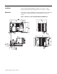
Installation The ArmorStart Distributed Motor Controller is convection cooled. Operating temperature must be kept between -20…40°C (-4…104°F). Dimensions Dimensions are shown in millimeters (inches). Dimensions are not intended to be used for manufacturing purposes. All dimensions are subject to change.
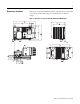
Dimensions, Continued Dimensions are shown in millimeters (inches). Dimensions are not intended to be used for manufacturing purposes. All dimensions are subject to change.
Wiring Power, Control, and Ground Wiring Table 1 provides the power, control, safety monitor inputs, and ground wire capacity and the tightening torque requirements. The power, control, and ground terminals will accept a maximum of two wires per terminal. Table 1 Terminal Designations Power, Control, Ground Wire Size, and Torque Specifications Terminals Wire Size Torque Wire Strip Length Three-phase Power and Ground Primary/Secondary Terminal: 1.5…4.0 mm2 (#16 …#10 AWG) Primary Terminal: 10.
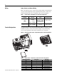
ArmorConnect Power Media Description The ArmorStart Power Media offers both three-phase and control power cable system of cordsets, patchcords, receptacles, tees, reducers and accessories to be utilized with the ArmorStart Distributed Motor Controller. These cable system components allow quick connection of ArmorStart Distributed Motor Controllers and reduce installation time.
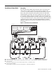
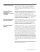
Figure 5 Control Power Media System Overview Enclosure PLC Bulletin 1492FB Branch Circuit Protective Device Bulletin 1606 Power Supply 1606-XLSDNET4 DeviceNet Power Supply Bulletin 280/281 ArmorStart Bulletin 280/281 ArmorStart RESET Bulletin 284 ArmorStart RESET ➏ Control Power Media Patchcords - PatchCord cable with integral female or male connector on each end Example Part Number: 889N-F3AFNU-*F ➐ Control Power Tees - The control power tee (Part Number: 898N-33PB-N4KF) is used to connect to the
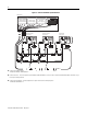
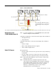
Figure 6 Safety System Overview Three-Phase Power Media DeviceNet Media I/O output I/O input The 1732DS Safety I/O module outputs to provided 24V DC power for control power to the ArmorStart - A1/A2 control power input Aux. Power The 1732DS Safety I/O module inputs will monitor the status of the safety-rated contactors inside the ArmorStart -SM safety monitor input.
ArmorStart Safety with ArmorConnect Connectivity A1/A2 -24V DC Safety Monitor Control Power from Input from 1732DS Safety 1732DS Safety I/O Module Output I/O Module Input Ground 120V AC Aux.
ArmorConnect Cable Ratings The ArmorConnect Power Media cables are rated per UL Type TC 600V 90 °C Dry 75 °C Wet, Exposed Run (ER) or MTW 600V 90 °C or STOOW 105 °C 600V - CSA STOOW 600V FT2. For additional information regarding ArmorConnect Power Media see the ArmorStart User Manual.
While the ArmorStart is intended for installation in factory floor environments of industrial establishments, the following must be taken into consideration when locating the ArmorStart in the application: Cables, including those for control voltage including 24V DC and communications, are not to be exposed to an operator or building traffic on a continuous basis. Location of the ArmorStart to minimize exposure to continual traffic is recommended.
Grounding Connect a grounding conductor to the terminal provided as standard on each ArmorStart Distributed Motor Controller. Refer to Table 2 for grounding provision location. There is also an externally available ground terminal. Refer to Figure 10. LED Status Indication The LED Status Indication provides 4 status LEDs and a Reset button.
DeviceNet Node Commissioning ATTENTION ! Three-phase power must be applied to the Bulletin 284G Distributed Motor Controller to gain access to drive parameters. Establishing a DeviceNet Node Address The ArmorStart is shipped with a default node address of 63 and Autobaud enabled. Each device on a DeviceNet network must have a unique node address or MAC ID which can be set to a value from 0…63.
Node Commissioning using Hardware The ArmorStart is shipped with the hardware rotary switches set to a value of (99). If the switches are set to a value of (64) or above, the device will automatically configure itself to the software node address. If the switches are set to a value of (63) or less, the device will be at the node address designated by the switch configuration. To set an address using the hardware rotary switches, simply set the switches to the desired node address.
Using Automap Feature with Default Input and Output (I/O) Assemblies The Automap feature available in all Rockwell Automation scanners will automatically map the information as shown below. If manual mapping is required, the information below can be used to map a device based on the default configuration.
Setting the Motor OL Current The product should now be configured and communicating on the network. The last step is to program the proper motor OL current setting (Parameter 133). This can be accomplished by using software such as RSNetWorx for DeviceNet or a handheld DeviceNet tool. Use the software to access the device parameters screen. By default the motor OL current is set to the minimum motor OL current setting for the device. Set this parameter to the desired value and download to the device.
Table 6 Basic Program Group for Sensorless Vector Control Parameter Number Parameter Description Display/ Options Min./ Max. Defaults Settings 131 ➊ Motor NP Volts 1 VAC 20/Drive Rated Volts Based on Driving Rating 132 ➊ Motor NP Hz 1 Hz 15/400 Hz 60 Hz 133 Motor OL Current 0.1 A 0.0/(Drive Rated Amps x 2) Based on Driving Rating 134 Minimum Freq. 0.1 Hz 0.0/400 Hz 0.0 Hz 135 ➊ Maximum Freq. 0.1 Hz 0.
Quick Reference Troubleshooting There are four LEDs on the front of the ArmorStart that can provide an indication as to the health of the device. The following is a brief explanation of the operation of each LED. Table 7 LED Status Indication LED Definition Power This LED will be illuminated solid green when control power is present and with the proper polarity. This LED will be illuminated solid green when a start command and control power are present.
Fault LED Indications for Bulletin 284G ArmorStart Distributed Motor Controllers Table 9 Controller Fault LED Definitions Fault Definitions Blink Pattern ArmorStart Drive Controlled 1 Short (140M) — 2 — Overload Fault (Drive Error Codes 7 and 64) 3 — Phase Short (Drive Error Codes 41…43) 4 — Ground Fault (Drive Error Codes 13, 38…40) 5 — Motor Stalled (Drive Error Code 6) Possible Causes or Remedies 6 Control Power — 7 I/O Fault — 8 — 9 — Heatsink Overtemperature (Drive
Internal Drive Faults A fault is a condition that stops the drive. There are two fault types. Table 10 Internal Drive Fault Types Type Description 1 Auto-Reset/Run When this type of fault occurs, and Parameter 192 (Auto Rstrt Tries) Related Parameter(s): 155, 158, 161, 193 is set to a value greater than 0, a user-configurable timer, Parameter 193 (AutoRstrt Delay) Related Parameter(s): 192, begins. When the timer reaches zero, the drive attempts to automatically reset the fault.
Table 11 Fault Types, Descriptions, and Actions No. Fault Type ➊ Description Action F2 Auxiliary Input 1 Auxiliary input interlock is open. 1. 2. Check remote wiring. Verify communications. F3 Power Loss 2 DC bus voltage remained below 85% of nominal. 1. 2. Monitor the incoming AC line for low voltage or line power interruption. Check input fuses. F4 UnderVoltage 1 DC bus voltage fell below the minimum value. Monitor the incoming AC line for low voltage or line power interruption.
Table 12 Fault Types, Descriptions, and Actions (Continued) No. Fault Type ➊ Description Action F48 Params Defaulted 2 The drive was commanded to write default values to EEPROM. 1. 2. Clear the fault or cycle power to the drive. Program the drive parameters as needed. F63 SW OverCurrent 2 Programmed Parameter 198 [SW Current Trip] has been exceeded. Check load requirements and Parameter 198 (SW Current Trip) setting. F64 Drive Overload 2 Drive rating of 150% for 1 min.
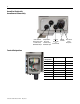
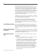
Figure 10 Bulletin 284G Safety ArmorStart Local Disconnect LED Status Indication 6 Inputs (Micro/M12) DeviceNet Connection (Mini/M18) A1/A2 SM Aux.
Accessories Table 12 DeviceNet Media ➊ 0 Description Length m (ft) Cat. No. Sealed KwikLink pigtail drops are Insulation Displacement Connector (IDC) with integral Class 1 round cables for interfacing devices or power supplies to flat cable DeviceNet Mini- T-Port Tap Gray PVC Thin Cable Thick Cable 1 m (3.3) 1485P-P1E4-B1-N5 2 m (6.5) 1485P-P1E4-B2-N5 3 m (9.8) 1485P-P1E4-B3-N5 6 m (19.8) 1485P-P1E4-B6-N5 Right Keyway Left Keyway 1485P-P1N5-MN5NF 1485P-P1N5-MN5KM Connector Cat. No.
Table 13 Sensor Media ➊ 0 Description ArmorStart I/O Connection Pin Count Connector Cat. No. Straight Female Straight Male 889D-F4ACDM-➋ Straight Female Right Angle Male 889D-F4AACDE-➋ Straight Female 879D-F4ACDM-➋ Right Angle Male 879D-R4ACM-➋ 0 Input 5-Pin 0 DC Micro Patchcord 0 Input 5-pin 0 DC Micro V-Cable ➊ See Publication M116-CA001A-EN-P for complete cable selection information. ➋ Replace symbol with desired length in meters (Example: 889D-F4ACDM-1 for a 1 m cable).
Notes: Publication 284GS-QS001A-EN-P - May 2009
Notes: Publication 284GS-QS001A-EN-P - May 2009
Notes: Publication 284GS-QS001A-EN-P - May 2009
Registered Trademark List ArmorPoint and ArmorStart are registered trademarks of Rockwell Automation, Inc. Trademark List ArmorConnect, RSLogix5000, PLC, RSNetWorx, and SLC are trademarks of Rockwell Automation, Inc. ControlNet is a trademark of ControlNet International, LTD. DeviceNet and the DeviceNet logo are trademarks of the Open Device Vendors Association (ODVA). Publication 284GS-QS001A-EN-P — May 2009 PN-29252 Copyright ©2009 Rockwell Automation, Inc. All Rights Reserved. Printed in USA.