
Instruction Manual
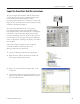
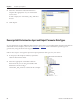
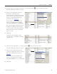
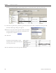
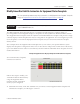
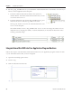
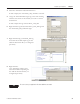
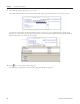
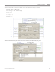
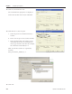
Table Of Contents
- Front Cover
- Important User Information
- Where to Start
- Table of Contents
- Preface
- Chapter 1
- Chapter 2
- System Layout and Wiring
- Before You Begin
- What You Need
- Follow These Steps
- Planning Your ArmorStart Panel Layout and Wiring
- Wiring Your ArmorStart Controllers
- Connecting the DeviceNet ArmorConnect to Your ArmorStart Device
- AC Supply Considerations for Bulletin 284 Units
- Group Motor Installations For North American and Canadian Markets
- Cabling and Installation Guidelines
- DeviceNet Network Installation
- Electromagnetic Compatibility
- System Layout and Wiring
- Chapter 3
- ArmorStart DeviceNet Configuration
- Before You Begin
- What You Need
- Follow These Steps
- Open an Existing Project in RSLogix 5000 Software
- Configure the DeviceNet Network by Using RSNetWorx Software
- Add a Scanner Module to Your ControlLogix Project
- Generate ArmorStart Tags by Using the Tag Generator Tool
- Download Controller File and Test ArmorStart Tags
- ArmorStart DeviceNet Configuration
- Chapter 4
- Chapter 5
- Faceplate Logix Integration
- Before You Begin
- What You Need
- Follow These Steps
- Import the ArmorStart Add-On Instructions
- Reassign Add-On Instruction Input and Output Parameter Data Types
- Modify ArmorStart Add-On Instruction for Equipment Status Faceplate
- Integrate ArmorStart AOI into Your Application Program Routines
- Integrate Your ArmorStart Device Application
- Add Alarm Logic for Alarm History Faceplate
- Download the Project
- Faceplate Logix Integration
- Chapter 6
- Chapter 7
- ArmorStart System Application Guide
- Before You Begin
- What You Need
- ArmorStart System Overview Display
- ArmorStart Device Faceplate Overview
- ArmorStart Device Faceplate - Fault Indication View
- Last Fault, Fault Description, and Fault Action
- ArmorStart Device Faceplate - Configuration Status View
- ArmorStart Device Faceplate - Trending View
- ArmorStart Device Faceplate - Online Help Options
- ArmorStart System Application Guide
- Appendix A
- Logix Communication and Controller Configuration
- Configuring PC Communication
- Configure the EtherNet/IP Driver
- Load the Controller Firmware Serially
- Assign IP Addresses
- Ethernet Module Firmware Update Using ControlFLASH Utility
- Browse the EtherNet/IP Network Devices
- Load the Controller Firmware
- Create a New Project File in RSLogix 5000 Software
- Configure Your Ethernet Module
- Logix Communication and Controller Configuration
- Appendix B
- Appendix C
- Back Cover/Rockwell Support
Publication IASIMP-QS015C-EN-P 93
Faceplate Logix Integration Chapter 5
3. Scroll to and select the Inp_ArmorStart_xxx AOI tag and click next to the Data Type field.
The Select Data Type dialog box opens.
4. Browse to the Input Data Type that
matches the ArmorStart type,
DeviceNet node, and data type that was
created when you generated tags for the
device, by using the DeviceNet tag
generator tool in Chapter
3.
It should have a name similar to the
device you configured, for example,
AB_284D_FHB2P3X10_I_85284B98.
If you have multiple ArmorStart devices
configured in RSLogix 5000 software,
you also need to create unique Add-On
Instruction files for those ArmorStart
devices as well.
5. Click OK.
The Data Type field updates. This
example shows a ArmorStart 284 input
tag’s data type.
6. Select the Out_ArmorStart_xx AOI tag and click next to the data type field.
The Select Data Type dialog box opens.
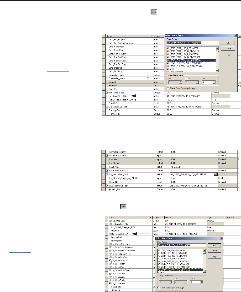
7. Browse to the output data type that
matches the Data Type that was created
when you configured the device in
Chapter 3.
It should have a name similar to the
device you configured, for example,
AB_284D-FHB2P3x_10_O_7B19C16B.
8. Click OK.