
Instruction Manual
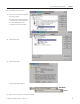
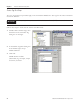
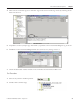
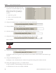
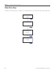
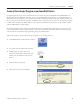
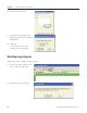
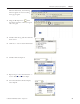
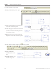
Table Of Contents
- Front Cover
- Important User Information
- Where to Start
- Table of Contents
- Preface
- Chapter 1
- Chapter 2
- System Layout and Wiring
- Before You Begin
- What You Need
- Follow These Steps
- Planning Your ArmorStart Panel Layout and Wiring
- Wiring Your ArmorStart Controllers
- Connecting the DeviceNet ArmorConnect to Your ArmorStart Device
- AC Supply Considerations for Bulletin 284 Units
- Group Motor Installations For North American and Canadian Markets
- Cabling and Installation Guidelines
- DeviceNet Network Installation
- Electromagnetic Compatibility
- System Layout and Wiring
- Chapter 3
- ArmorStart DeviceNet Configuration
- Before You Begin
- What You Need
- Follow These Steps
- Open an Existing Project in RSLogix 5000 Software
- Configure the DeviceNet Network by Using RSNetWorx Software
- Add a Scanner Module to Your ControlLogix Project
- Generate ArmorStart Tags by Using the Tag Generator Tool
- Download Controller File and Test ArmorStart Tags
- ArmorStart DeviceNet Configuration
- Chapter 4
- Chapter 5
- Faceplate Logix Integration
- Before You Begin
- What You Need
- Follow These Steps
- Import the ArmorStart Add-On Instructions
- Reassign Add-On Instruction Input and Output Parameter Data Types
- Modify ArmorStart Add-On Instruction for Equipment Status Faceplate
- Integrate ArmorStart AOI into Your Application Program Routines
- Integrate Your ArmorStart Device Application
- Add Alarm Logic for Alarm History Faceplate
- Download the Project
- Faceplate Logix Integration
- Chapter 6
- Chapter 7
- ArmorStart System Application Guide
- Before You Begin
- What You Need
- ArmorStart System Overview Display
- ArmorStart Device Faceplate Overview
- ArmorStart Device Faceplate - Fault Indication View
- Last Fault, Fault Description, and Fault Action
- ArmorStart Device Faceplate - Configuration Status View
- ArmorStart Device Faceplate - Trending View
- ArmorStart Device Faceplate - Online Help Options
- ArmorStart System Application Guide
- Appendix A
- Logix Communication and Controller Configuration
- Configuring PC Communication
- Configure the EtherNet/IP Driver
- Load the Controller Firmware Serially
- Assign IP Addresses
- Ethernet Module Firmware Update Using ControlFLASH Utility
- Browse the EtherNet/IP Network Devices
- Load the Controller Firmware
- Create a New Project File in RSLogix 5000 Software
- Configure Your Ethernet Module
- Logix Communication and Controller Configuration
- Appendix B
- Appendix C
- Back Cover/Rockwell Support
74 Publication IASIMP-QS015C-EN-P - August 2011
Chapter 3 ArmorStart DeviceNet Configuration
3. From the Monitor Tags tab, locate and
expand the ArmorStart 284D output tags.
Follow this procedure if you need to
change the value of a tag in RSLogix
software.
a. Select the tag value.
b. Enter or select the desire value.
c. Press Enter.
4. Change the FaultReset tag to 1 and press Enter to clear any initial faults.
5. Change FaultReset back to 0 and press enter.
6. Verify that the I.Status_ready tag value is 1, indicating that the device is ready.
7. Change the O.CommandFreq tag to 600 engineering units and press Enter.
This is 60.0 Hz.
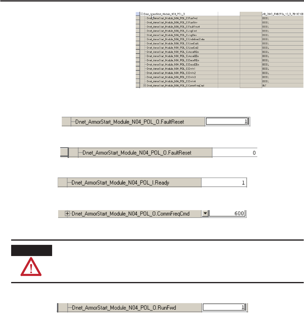
8. Change the RunFwd tag to 1 and press Enter.
The display on the device registers the speed increase in Hz until the value entered at the reference tag is
reached.
9. Change the RunFwd tag back to 0.
The display on the ArmorStart device will show the speed decreasing until it reaches 0.00 Hz.
By starting and stopping the device, you verified that the:
• Logix controller is communicating correctly with the device.
• ArmorStart device can receive simple commands.
ATTENTION
If there is a motor attached to your device, completing the next step will cause it to turn.