
Instruction Manual
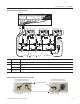
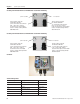
Table Of Contents
- Front Cover
- Important User Information
- Where to Start
- Table of Contents
- Preface
- Chapter 1
- Chapter 2
- System Layout and Wiring
- Before You Begin
- What You Need
- Follow These Steps
- Planning Your ArmorStart Panel Layout and Wiring
- Wiring Your ArmorStart Controllers
- Connecting the DeviceNet ArmorConnect to Your ArmorStart Device
- AC Supply Considerations for Bulletin 284 Units
- Group Motor Installations For North American and Canadian Markets
- Cabling and Installation Guidelines
- DeviceNet Network Installation
- Electromagnetic Compatibility
- System Layout and Wiring
- Chapter 3
- ArmorStart DeviceNet Configuration
- Before You Begin
- What You Need
- Follow These Steps
- Open an Existing Project in RSLogix 5000 Software
- Configure the DeviceNet Network by Using RSNetWorx Software
- Add a Scanner Module to Your ControlLogix Project
- Generate ArmorStart Tags by Using the Tag Generator Tool
- Download Controller File and Test ArmorStart Tags
- ArmorStart DeviceNet Configuration
- Chapter 4
- Chapter 5
- Faceplate Logix Integration
- Before You Begin
- What You Need
- Follow These Steps
- Import the ArmorStart Add-On Instructions
- Reassign Add-On Instruction Input and Output Parameter Data Types
- Modify ArmorStart Add-On Instruction for Equipment Status Faceplate
- Integrate ArmorStart AOI into Your Application Program Routines
- Integrate Your ArmorStart Device Application
- Add Alarm Logic for Alarm History Faceplate
- Download the Project
- Faceplate Logix Integration
- Chapter 6
- Chapter 7
- ArmorStart System Application Guide
- Before You Begin
- What You Need
- ArmorStart System Overview Display
- ArmorStart Device Faceplate Overview
- ArmorStart Device Faceplate - Fault Indication View
- Last Fault, Fault Description, and Fault Action
- ArmorStart Device Faceplate - Configuration Status View
- ArmorStart Device Faceplate - Trending View
- ArmorStart Device Faceplate - Online Help Options
- ArmorStart System Application Guide
- Appendix A
- Logix Communication and Controller Configuration
- Configuring PC Communication
- Configure the EtherNet/IP Driver
- Load the Controller Firmware Serially
- Assign IP Addresses
- Ethernet Module Firmware Update Using ControlFLASH Utility
- Browse the EtherNet/IP Network Devices
- Load the Controller Firmware
- Create a New Project File in RSLogix 5000 Software
- Configure Your Ethernet Module
- Logix Communication and Controller Configuration
- Appendix B
- Appendix C
- Back Cover/Rockwell Support

Publication IASIMP-QS015C-EN-P - August 2011 55
System Layout and Wiring Chapter 2
Since the ArmorStart device is available with a factory installed HOA keypad option, this may require the
ArmorStart device to be selected and installed as follows. If the application requires frequent use of the
hand-operated interface by the equipment operator:
• they should not be less than 0.6 m (2 ft) above the servicing level and are within easy reach of the
normal working position of the operator.
• the operator is not placed in a hazardous situation when operating them.
• the possibility of inadvertent operation is minimized.
If the operated interface is used in industrial environments where the conditions of maintenance and
supervision ensure that only qualified persons operate and service the ArmorStart operator interface, and the
installation is located so that inadvertent operation is minimized, then other installation locations with
acceptable access can be provided.
DeviceNet Network Installation
The ArmorStart distributed motor controller contains the equivalent of 0.76 m (30 in) of DeviceNet drop
cable's electrical characteristics and therefore 0.76 m (30 in) of drop cable must be included in the DeviceNet
drop cable budget for each ArmorStart controller in addition to actual drop cable required for the
installation.
The separation of the control power and DeviceNet power is recommended as a good design practice. This
minimizes the load on the DeviceNet supply, and prevents transients which may be present on the control
power system from influencing the communication controls.