
Instruction Manual
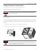
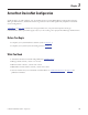
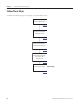
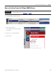
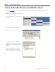
Table Of Contents
- Front Cover
- Important User Information
- Where to Start
- Table of Contents
- Preface
- Chapter 1
- Chapter 2
- System Layout and Wiring
- Before You Begin
- What You Need
- Follow These Steps
- Planning Your ArmorStart Panel Layout and Wiring
- Wiring Your ArmorStart Controllers
- Connecting the DeviceNet ArmorConnect to Your ArmorStart Device
- AC Supply Considerations for Bulletin 284 Units
- Group Motor Installations For North American and Canadian Markets
- Cabling and Installation Guidelines
- DeviceNet Network Installation
- Electromagnetic Compatibility
- System Layout and Wiring
- Chapter 3
- ArmorStart DeviceNet Configuration
- Before You Begin
- What You Need
- Follow These Steps
- Open an Existing Project in RSLogix 5000 Software
- Configure the DeviceNet Network by Using RSNetWorx Software
- Add a Scanner Module to Your ControlLogix Project
- Generate ArmorStart Tags by Using the Tag Generator Tool
- Download Controller File and Test ArmorStart Tags
- ArmorStart DeviceNet Configuration
- Chapter 4
- Chapter 5
- Faceplate Logix Integration
- Before You Begin
- What You Need
- Follow These Steps
- Import the ArmorStart Add-On Instructions
- Reassign Add-On Instruction Input and Output Parameter Data Types
- Modify ArmorStart Add-On Instruction for Equipment Status Faceplate
- Integrate ArmorStart AOI into Your Application Program Routines
- Integrate Your ArmorStart Device Application
- Add Alarm Logic for Alarm History Faceplate
- Download the Project
- Faceplate Logix Integration
- Chapter 6
- Chapter 7
- ArmorStart System Application Guide
- Before You Begin
- What You Need
- ArmorStart System Overview Display
- ArmorStart Device Faceplate Overview
- ArmorStart Device Faceplate - Fault Indication View
- Last Fault, Fault Description, and Fault Action
- ArmorStart Device Faceplate - Configuration Status View
- ArmorStart Device Faceplate - Trending View
- ArmorStart Device Faceplate - Online Help Options
- ArmorStart System Application Guide
- Appendix A
- Logix Communication and Controller Configuration
- Configuring PC Communication
- Configure the EtherNet/IP Driver
- Load the Controller Firmware Serially
- Assign IP Addresses
- Ethernet Module Firmware Update Using ControlFLASH Utility
- Browse the EtherNet/IP Network Devices
- Load the Controller Firmware
- Create a New Project File in RSLogix 5000 Software
- Configure Your Ethernet Module
- Logix Communication and Controller Configuration
- Appendix B
- Appendix C
- Back Cover/Rockwell Support

54 Publication IASIMP-QS015C-EN-P - August 2011
Chapter 2 System Layout and Wiring
Group Motor Installations For North American and Canadian Markets
The ArmorStart distributed motor controllers are listed for use with each other in group installations per
NFPA 79, Electrical Standard for Industrial Machinery. When applied according to the group motor
installation requirements, two or more motors, of any rating or controller type, are permitted on a single
branch circuit. Group motor installation has been successfully used for many years in North America and
Canada.
Cabling and Installation Guidelines
In addition to conduit and seal-tight raceway, it is acceptable to use cable that is dual rated Tray Cable, Type
TC-ER and Cord, STOOW, for power and control wiring on ArmorStart installations. In North America and
Canada installations, the following guidelines are outlined by the NEC and NFPA 79.
In industrial environments where the conditions of maintenance and supervision ensure that only qualified
personnel service the installation, and where the exposed cable is continuously supported and protected
against physical damage by using mechanical protection, such as struts, angles, or channels, Type TC tray
cable that complies with the crush and impact requirements of type metal clad (MC) cable and is identified
for such use with the marking type TC-ER (Exposed Run) shall be permitted between a cable tray and the
use equipment or device as open wiring. The cable shall be secured at intervals not exceeding 1.8 m (6 ft) and
installed in a ‘good workman-like’ manner. Equipment grounding for the use equipment shall be provided by
an equipment grounding conductor within the cable.
Cables meeting these crush and impact requirements were designated and marked ‘Open Wiring’. Cable
marked this way is equivalent to the present Type TC-ER and can be used.
Refer to the following when installing the ArmorStart device in factory floor environments of industrial
applications.
Additionally, if conduit or other raceways are not used, we recommend that strain relief fittings be used when
installing the cables for the control and power wiring through the conduit openings.
The working space around the ArmorStart device may be minimized as the ArmorStart device does not
require examination, adjustment, servicing, or maintenance while energized. In lieu of this service, the
ArmorStart device is meant to be unplugged and replaced after proper lockout and tag-out procedures have
been employed.
ATTENTION
Cables, including those for control voltage including 24V DC and communication, are not to be exposed to
an operator or building traffic on a continuous basis. Locate the ArmorStart device to minimize exposure to
continual traffic is recommended. If the location to minimize traffic flow is unavoidable, other barriers to
minimize inadvertent exposure to the cabling should be considered. Routing cables should be done in such
a manner to minimize inadvertent exposure and/or damage.