
Instruction Manual
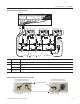
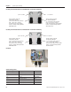
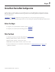
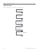
Table Of Contents
- Front Cover
- Important User Information
- Where to Start
- Table of Contents
- Preface
- Chapter 1
- Chapter 2
- System Layout and Wiring
- Before You Begin
- What You Need
- Follow These Steps
- Planning Your ArmorStart Panel Layout and Wiring
- Wiring Your ArmorStart Controllers
- Connecting the DeviceNet ArmorConnect to Your ArmorStart Device
- AC Supply Considerations for Bulletin 284 Units
- Group Motor Installations For North American and Canadian Markets
- Cabling and Installation Guidelines
- DeviceNet Network Installation
- Electromagnetic Compatibility
- System Layout and Wiring
- Chapter 3
- ArmorStart DeviceNet Configuration
- Before You Begin
- What You Need
- Follow These Steps
- Open an Existing Project in RSLogix 5000 Software
- Configure the DeviceNet Network by Using RSNetWorx Software
- Add a Scanner Module to Your ControlLogix Project
- Generate ArmorStart Tags by Using the Tag Generator Tool
- Download Controller File and Test ArmorStart Tags
- ArmorStart DeviceNet Configuration
- Chapter 4
- Chapter 5
- Faceplate Logix Integration
- Before You Begin
- What You Need
- Follow These Steps
- Import the ArmorStart Add-On Instructions
- Reassign Add-On Instruction Input and Output Parameter Data Types
- Modify ArmorStart Add-On Instruction for Equipment Status Faceplate
- Integrate ArmorStart AOI into Your Application Program Routines
- Integrate Your ArmorStart Device Application
- Add Alarm Logic for Alarm History Faceplate
- Download the Project
- Faceplate Logix Integration
- Chapter 6
- Chapter 7
- ArmorStart System Application Guide
- Before You Begin
- What You Need
- ArmorStart System Overview Display
- ArmorStart Device Faceplate Overview
- ArmorStart Device Faceplate - Fault Indication View
- Last Fault, Fault Description, and Fault Action
- ArmorStart Device Faceplate - Configuration Status View
- ArmorStart Device Faceplate - Trending View
- ArmorStart Device Faceplate - Online Help Options
- ArmorStart System Application Guide
- Appendix A
- Logix Communication and Controller Configuration
- Configuring PC Communication
- Configure the EtherNet/IP Driver
- Load the Controller Firmware Serially
- Assign IP Addresses
- Ethernet Module Firmware Update Using ControlFLASH Utility
- Browse the EtherNet/IP Network Devices
- Load the Controller Firmware
- Create a New Project File in RSLogix 5000 Software
- Configure Your Ethernet Module
- Logix Communication and Controller Configuration
- Appendix B
- Appendix C
- Back Cover/Rockwell Support
Publication IASIMP-QS015C-EN-P - August 2011 51
System Layout and Wiring Chapter 2
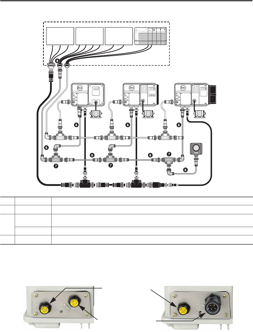
Control Power Media System Overview
ArmorStart Device with ArmorConnect Connectivity
ID Cat. No. Description
6
889N-F65GFNM-x
1
1
“x” represents number needed for desired cable length, which is 2 (2 meters/6.5 feet), 5 (5 m/16.4 ft), or 10 (10 m/32.8 ft).
Control power media patchcords - Patchcord cable with integral female or male connector on each end.
7
898N-653ST-NKF
The E-stop in tee used to connect to the Bulletin 800F On-Machine E-Stop station by using a control power media
patchcord.
898N-653ES-NKF The E-stop out tee is used with cordset or patchcord to connect to the ArmorStart distributed motor controller.
8
888N-D65AF1-x
1
Control power receptacles - Female receptacles are a panel mount connector with flying leads.
RESET
OFF
Bulletin 280/281 ArmorStart
Bulletin 283 ArmorStart
Bulletin 284 ArmorStart
PLC
Bulletin 1492FB
Branch Circuit
Protective Device
Bulletin 1606
Power Supply
Enclosure
Bulletin 800F
Emergency Stop
Pushbutton
1606-XLSDNET4
DeviceNet
Power Supply
ArmorStart Devices with 10 A
Short-circuit Protection Rating
ArmorStart Devices with 25 A
Short-circuit Protection Rating
Control Power Receptacle
Three-phase Power Receptacle