
Instruction Manual
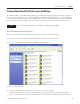
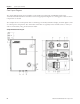
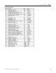
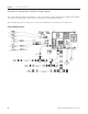
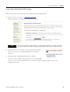
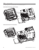
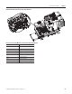
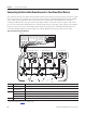
Table Of Contents
- Front Cover
- Important User Information
- Where to Start
- Table of Contents
- Preface
- Chapter 1
- Chapter 2
- System Layout and Wiring
- Before You Begin
- What You Need
- Follow These Steps
- Planning Your ArmorStart Panel Layout and Wiring
- Wiring Your ArmorStart Controllers
- Connecting the DeviceNet ArmorConnect to Your ArmorStart Device
- AC Supply Considerations for Bulletin 284 Units
- Group Motor Installations For North American and Canadian Markets
- Cabling and Installation Guidelines
- DeviceNet Network Installation
- Electromagnetic Compatibility
- System Layout and Wiring
- Chapter 3
- ArmorStart DeviceNet Configuration
- Before You Begin
- What You Need
- Follow These Steps
- Open an Existing Project in RSLogix 5000 Software
- Configure the DeviceNet Network by Using RSNetWorx Software
- Add a Scanner Module to Your ControlLogix Project
- Generate ArmorStart Tags by Using the Tag Generator Tool
- Download Controller File and Test ArmorStart Tags
- ArmorStart DeviceNet Configuration
- Chapter 4
- Chapter 5
- Faceplate Logix Integration
- Before You Begin
- What You Need
- Follow These Steps
- Import the ArmorStart Add-On Instructions
- Reassign Add-On Instruction Input and Output Parameter Data Types
- Modify ArmorStart Add-On Instruction for Equipment Status Faceplate
- Integrate ArmorStart AOI into Your Application Program Routines
- Integrate Your ArmorStart Device Application
- Add Alarm Logic for Alarm History Faceplate
- Download the Project
- Faceplate Logix Integration
- Chapter 6
- Chapter 7
- ArmorStart System Application Guide
- Before You Begin
- What You Need
- ArmorStart System Overview Display
- ArmorStart Device Faceplate Overview
- ArmorStart Device Faceplate - Fault Indication View
- Last Fault, Fault Description, and Fault Action
- ArmorStart Device Faceplate - Configuration Status View
- ArmorStart Device Faceplate - Trending View
- ArmorStart Device Faceplate - Online Help Options
- ArmorStart System Application Guide
- Appendix A
- Logix Communication and Controller Configuration
- Configuring PC Communication
- Configure the EtherNet/IP Driver
- Load the Controller Firmware Serially
- Assign IP Addresses
- Ethernet Module Firmware Update Using ControlFLASH Utility
- Browse the EtherNet/IP Network Devices
- Load the Controller Firmware
- Create a New Project File in RSLogix 5000 Software
- Configure Your Ethernet Module
- Logix Communication and Controller Configuration
- Appendix B
- Appendix C
- Back Cover/Rockwell Support

Publication IASIMP-QS015C-EN-P - August 2011 47
System Layout and Wiring Chapter 2
ArmorStart Device Wiring
Wiring in an industrial control application can be divided into three groups; power, control, and signal.
Follow these recommendations for physical separation between these to reduce the coupling effect:
• Minimum spacing between different wire groups in the same tray should be 16 cm (6 in.).
• Run wire outside an enclosure conduit or have shielding or armor with equivalent attenuation.
• Run different wire groups in separate conduits.
• Minimum spacing between conduits containing different groups should be 8 cm (3 in.).
The table provides power, control, ground wire capacity, and tightening torque requirements. The power,
control, ground, and safety monitor terminals accept a maximum of two-wire per terminal.
Power, Control, Safety Monitor Inputs, Ground Wire Size, and Torque Specifications
Terminal Type Wire Size Torque Wire Strip Length
Power and Ground Primary/secondary terminal
1.5...4.0 mm
2
(16...10 AWG)
Primary terminal - 1.2 N•m (10.8 lb•in.)
Secondary terminal - 0.5 N•m (4.5 lb•in.)
9 mm (0.35 in)
Control and Safety Monitor Inputs
1.0...4.0 mm
2
(18...10 AWG)
0.7 N•m (6.2 lb•in.) 9 mm (0.35 in.)