
Instruction Manual
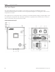
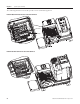
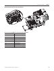
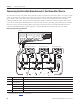
Table Of Contents
- Front Cover
- Important User Information
- Where to Start
- Table of Contents
- Preface
- Chapter 1
- Chapter 2
- System Layout and Wiring
- Before You Begin
- What You Need
- Follow These Steps
- Planning Your ArmorStart Panel Layout and Wiring
- Wiring Your ArmorStart Controllers
- Connecting the DeviceNet ArmorConnect to Your ArmorStart Device
- AC Supply Considerations for Bulletin 284 Units
- Group Motor Installations For North American and Canadian Markets
- Cabling and Installation Guidelines
- DeviceNet Network Installation
- Electromagnetic Compatibility
- System Layout and Wiring
- Chapter 3
- ArmorStart DeviceNet Configuration
- Before You Begin
- What You Need
- Follow These Steps
- Open an Existing Project in RSLogix 5000 Software
- Configure the DeviceNet Network by Using RSNetWorx Software
- Add a Scanner Module to Your ControlLogix Project
- Generate ArmorStart Tags by Using the Tag Generator Tool
- Download Controller File and Test ArmorStart Tags
- ArmorStart DeviceNet Configuration
- Chapter 4
- Chapter 5
- Faceplate Logix Integration
- Before You Begin
- What You Need
- Follow These Steps
- Import the ArmorStart Add-On Instructions
- Reassign Add-On Instruction Input and Output Parameter Data Types
- Modify ArmorStart Add-On Instruction for Equipment Status Faceplate
- Integrate ArmorStart AOI into Your Application Program Routines
- Integrate Your ArmorStart Device Application
- Add Alarm Logic for Alarm History Faceplate
- Download the Project
- Faceplate Logix Integration
- Chapter 6
- Chapter 7
- ArmorStart System Application Guide
- Before You Begin
- What You Need
- ArmorStart System Overview Display
- ArmorStart Device Faceplate Overview
- ArmorStart Device Faceplate - Fault Indication View
- Last Fault, Fault Description, and Fault Action
- ArmorStart Device Faceplate - Configuration Status View
- ArmorStart Device Faceplate - Trending View
- ArmorStart Device Faceplate - Online Help Options
- ArmorStart System Application Guide
- Appendix A
- Logix Communication and Controller Configuration
- Configuring PC Communication
- Configure the EtherNet/IP Driver
- Load the Controller Firmware Serially
- Assign IP Addresses
- Ethernet Module Firmware Update Using ControlFLASH Utility
- Browse the EtherNet/IP Network Devices
- Load the Controller Firmware
- Create a New Project File in RSLogix 5000 Software
- Configure Your Ethernet Module
- Logix Communication and Controller Configuration
- Appendix B
- Appendix C
- Back Cover/Rockwell Support
46 Publication IASIMP-QS015C-EN-P - August 2011
Chapter 2 System Layout and Wiring
Wiring Your ArmorStart Controllers
This section provides information pertaining to wiring your ArmorStart distributive motor controller.
General Precautions
Additional Precautions for the Bulletin 284 Devices
ATTENTION
The controller contains electrostatic discharge (ESD) sensitive parts and assemblies. Static control
precautions are required when installing, testing, servicing, or repairing the assembly. Component damage
may result if the ESD control procedures are not followed. If you are not familiar with static control
procedures, refer to Guarding Against Electrostatic Discharge, publication 8000-SB001
, or any other ESD
protection documents.
ATTENTION
An incorrectly applied or installed controller can damage components or reduce product life. Wiring or
application errors, such as an undersized motor, incorrect or inadequate AC supply, or excessive ambient
temperatures, may result in malfunction of the system.
ATTENTION
Only personnel familiar with the controller and associated machinery should plan or implement the
installation, startup, and subsequent maintenance of the system. Failure to do so may result in personal
injury and equipment damage.
ATTENTION
The ArmorStart device contains high-voltage capacitors which take time to discharge after removel of
mains supply. Before working on an ArmorStart device, help ensure isolation of mains supply from line
inputs [R, S, T (L1, L2, and L3)]. Wait at least three minutes for the capacitors to discharge to a safe voltage
level. Failure to do so may result in personal injury or death. Darkened display indicators are not an
indication that the capacitors have discharged to safe levels.
Only qualified personnel familiar with ArmorStart devices and associated machinery should plan or
implement the installation, startup, and subsequent maintenance of the system. Failure to do so may result
in personal injury and equipment damage.