
Instruction Manual
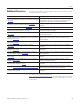

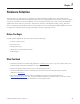
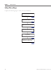
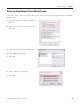
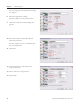
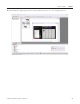
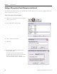
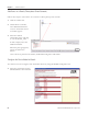
Table Of Contents
- Front Cover
- Important User Information
- Where to Start
- Table of Contents
- Preface
- Chapter 1
- Chapter 2
- System Layout and Wiring
- Before You Begin
- What You Need
- Follow These Steps
- Planning Your ArmorStart Panel Layout and Wiring
- Wiring Your ArmorStart Controllers
- Connecting the DeviceNet ArmorConnect to Your ArmorStart Device
- AC Supply Considerations for Bulletin 284 Units
- Group Motor Installations For North American and Canadian Markets
- Cabling and Installation Guidelines
- DeviceNet Network Installation
- Electromagnetic Compatibility
- System Layout and Wiring
- Chapter 3
- ArmorStart DeviceNet Configuration
- Before You Begin
- What You Need
- Follow These Steps
- Open an Existing Project in RSLogix 5000 Software
- Configure the DeviceNet Network by Using RSNetWorx Software
- Add a Scanner Module to Your ControlLogix Project
- Generate ArmorStart Tags by Using the Tag Generator Tool
- Download Controller File and Test ArmorStart Tags
- ArmorStart DeviceNet Configuration
- Chapter 4
- Chapter 5
- Faceplate Logix Integration
- Before You Begin
- What You Need
- Follow These Steps
- Import the ArmorStart Add-On Instructions
- Reassign Add-On Instruction Input and Output Parameter Data Types
- Modify ArmorStart Add-On Instruction for Equipment Status Faceplate
- Integrate ArmorStart AOI into Your Application Program Routines
- Integrate Your ArmorStart Device Application
- Add Alarm Logic for Alarm History Faceplate
- Download the Project
- Faceplate Logix Integration
- Chapter 6
- Chapter 7
- ArmorStart System Application Guide
- Before You Begin
- What You Need
- ArmorStart System Overview Display
- ArmorStart Device Faceplate Overview
- ArmorStart Device Faceplate - Fault Indication View
- Last Fault, Fault Description, and Fault Action
- ArmorStart Device Faceplate - Configuration Status View
- ArmorStart Device Faceplate - Trending View
- ArmorStart Device Faceplate - Online Help Options
- ArmorStart System Application Guide
- Appendix A
- Logix Communication and Controller Configuration
- Configuring PC Communication
- Configure the EtherNet/IP Driver
- Load the Controller Firmware Serially
- Assign IP Addresses
- Ethernet Module Firmware Update Using ControlFLASH Utility
- Browse the EtherNet/IP Network Devices
- Load the Controller Firmware
- Create a New Project File in RSLogix 5000 Software
- Configure Your Ethernet Module
- Logix Communication and Controller Configuration
- Appendix B
- Appendix C
- Back Cover/Rockwell Support
Publication IASIMP-QS015C-EN-P - August 2011 19
Hardware Selection Chapter 1
6. From the Control Voltage pull-down menu,
choose 24VDC.
This will be the default control voltage for
ArmorStart motor controllers connected to
the network. Other options are 120V AC and
240V AC. Control voltage might be
distributed by a Control Power network,
which you can also configure in the IAB
software.
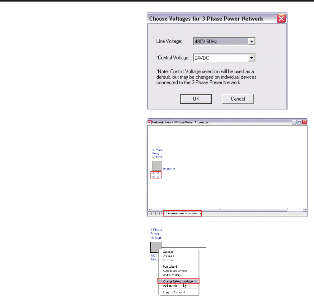
A new three-phase power network is created
with a single branch and displayed in the
network view. Notice the tab added to the
network view and the display of the network
voltage. The gray box at the left end of the
network represents the power distribution
panel.
You can change the three-phase power
network voltage if needed by right-clicking
the distribution panel (the box at the left end
of the network) and choosing Change
Network Voltage.