
Instruction Manual
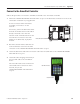

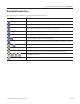
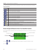
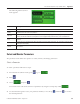
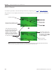
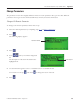
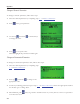

Table Of Contents
- Front Cover
- Important User Information
- Where to Start
- Table of Contents
- Preface
- Chapter 1
- Chapter 2
- System Layout and Wiring
- Before You Begin
- What You Need
- Follow These Steps
- Planning Your ArmorStart Panel Layout and Wiring
- Wiring Your ArmorStart Controllers
- Connecting the DeviceNet ArmorConnect to Your ArmorStart Device
- AC Supply Considerations for Bulletin 284 Units
- Group Motor Installations For North American and Canadian Markets
- Cabling and Installation Guidelines
- DeviceNet Network Installation
- Electromagnetic Compatibility
- System Layout and Wiring
- Chapter 3
- ArmorStart DeviceNet Configuration
- Before You Begin
- What You Need
- Follow These Steps
- Open an Existing Project in RSLogix 5000 Software
- Configure the DeviceNet Network by Using RSNetWorx Software
- Add a Scanner Module to Your ControlLogix Project
- Generate ArmorStart Tags by Using the Tag Generator Tool
- Download Controller File and Test ArmorStart Tags
- ArmorStart DeviceNet Configuration
- Chapter 4
- Chapter 5
- Faceplate Logix Integration
- Before You Begin
- What You Need
- Follow These Steps
- Import the ArmorStart Add-On Instructions
- Reassign Add-On Instruction Input and Output Parameter Data Types
- Modify ArmorStart Add-On Instruction for Equipment Status Faceplate
- Integrate ArmorStart AOI into Your Application Program Routines
- Integrate Your ArmorStart Device Application
- Add Alarm Logic for Alarm History Faceplate
- Download the Project
- Faceplate Logix Integration
- Chapter 6
- Chapter 7
- ArmorStart System Application Guide
- Before You Begin
- What You Need
- ArmorStart System Overview Display
- ArmorStart Device Faceplate Overview
- ArmorStart Device Faceplate - Fault Indication View
- Last Fault, Fault Description, and Fault Action
- ArmorStart Device Faceplate - Configuration Status View
- ArmorStart Device Faceplate - Trending View
- ArmorStart Device Faceplate - Online Help Options
- ArmorStart System Application Guide
- Appendix A
- Logix Communication and Controller Configuration
- Configuring PC Communication
- Configure the EtherNet/IP Driver
- Load the Controller Firmware Serially
- Assign IP Addresses
- Ethernet Module Firmware Update Using ControlFLASH Utility
- Browse the EtherNet/IP Network Devices
- Load the Controller Firmware
- Create a New Project File in RSLogix 5000 Software
- Configure Your Ethernet Module
- Logix Communication and Controller Configuration
- Appendix B
- Appendix C
- Back Cover/Rockwell Support
182 Publication IASIMP-QS015C-EN-P - August 2011
Appendix C ArmorStart Configuration Using 193-DNCT Device
The following table describes the alternate functionality of each key when it is pressed after the Shift key.
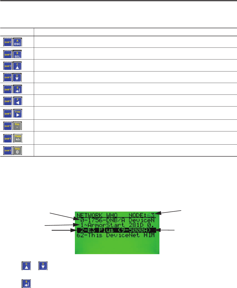
Browse through the Network to Select Your ArmorStart Controller
The terminal searches for all devices on the network and reports the devices it has found on the Network
Who display.
1. Press or to scroll through devices until you find the ArmorStart controller you need.
2. Press .
Alternate Functionality
Key Sequence Description
The letter A. Used to enter values in hexadecimal.
The letter B. Used to enter values in hexadecimal.
The letter C. Used to enter values in hexadecimal.
The letter D. Used to enter values in hexadecimal.
The letter E. Used to enter values in hexadecimal.
The letter F. Used to enter values in hexadecimal.
Copy function. Used to copy Class, Instance, and/or Attribute data to the clipboard. Available on screens displaying a
small ‘C’ in the upper right corner.
Exponential function. Used to enter values in exponential notation.
Paste function. Used to paste Class, Instance, and/or Attribute data from the clipboard. Available on screens
displaying a small ‘P’ in the upper right corner.
Help function. Invoke help information for the current screen.
Searching At This Address
Currently Selected Device
Device Address
“~” = Device Is Faulted
“–“ = Device Is Not Faulted