
Instruction Manual

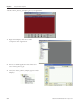


Table Of Contents
- Front Cover
- Important User Information
- Where to Start
- Table of Contents
- Preface
- Chapter 1
- Chapter 2
- System Layout and Wiring
- Before You Begin
- What You Need
- Follow These Steps
- Planning Your ArmorStart Panel Layout and Wiring
- Wiring Your ArmorStart Controllers
- Connecting the DeviceNet ArmorConnect to Your ArmorStart Device
- AC Supply Considerations for Bulletin 284 Units
- Group Motor Installations For North American and Canadian Markets
- Cabling and Installation Guidelines
- DeviceNet Network Installation
- Electromagnetic Compatibility
- System Layout and Wiring
- Chapter 3
- ArmorStart DeviceNet Configuration
- Before You Begin
- What You Need
- Follow These Steps
- Open an Existing Project in RSLogix 5000 Software
- Configure the DeviceNet Network by Using RSNetWorx Software
- Add a Scanner Module to Your ControlLogix Project
- Generate ArmorStart Tags by Using the Tag Generator Tool
- Download Controller File and Test ArmorStart Tags
- ArmorStart DeviceNet Configuration
- Chapter 4
- Chapter 5
- Faceplate Logix Integration
- Before You Begin
- What You Need
- Follow These Steps
- Import the ArmorStart Add-On Instructions
- Reassign Add-On Instruction Input and Output Parameter Data Types
- Modify ArmorStart Add-On Instruction for Equipment Status Faceplate
- Integrate ArmorStart AOI into Your Application Program Routines
- Integrate Your ArmorStart Device Application
- Add Alarm Logic for Alarm History Faceplate
- Download the Project
- Faceplate Logix Integration
- Chapter 6
- Chapter 7
- ArmorStart System Application Guide
- Before You Begin
- What You Need
- ArmorStart System Overview Display
- ArmorStart Device Faceplate Overview
- ArmorStart Device Faceplate - Fault Indication View
- Last Fault, Fault Description, and Fault Action
- ArmorStart Device Faceplate - Configuration Status View
- ArmorStart Device Faceplate - Trending View
- ArmorStart Device Faceplate - Online Help Options
- ArmorStart System Application Guide
- Appendix A
- Logix Communication and Controller Configuration
- Configuring PC Communication
- Configure the EtherNet/IP Driver
- Load the Controller Firmware Serially
- Assign IP Addresses
- Ethernet Module Firmware Update Using ControlFLASH Utility
- Browse the EtherNet/IP Network Devices
- Load the Controller Firmware
- Create a New Project File in RSLogix 5000 Software
- Configure Your Ethernet Module
- Logix Communication and Controller Configuration
- Appendix B
- Appendix C
- Back Cover/Rockwell Support
Publication IASIMP-QS015C-EN-P - August 2011 133
FactoryTalk View Integration Chapter 6
Add Alarm History Faceplate
The ME Alarm History Faceplate files let you quickly load and configure a pre-configured Alarm History
display or faceplate for FactoryTalk View Machine Edition software. The Alarm History Faceplate works in
conjunction with the individual ME_ArmorStart_Faceplates, ME_PowerFlex_Faceplates/AOIs,
ME_Kinetix_Faceplates/AOIs, and ME_E3 Plus_Faceplates/AOIs, and provides an Alarm History of all of
the device alarms and warnings that are configured to its alarm triggers. The Alarm History Faceplate files
include pre-configured alarm triggers and messages for the ArmorStart devices, Kinetix Motion Axis, and E3
Plus Overload Relay family of devices.
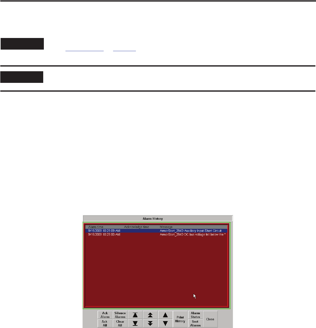
In this example, an Alarm History Faceplate is displaying alarms/faults from ArmorStart devices (Motor 1
and Motor 2). The pre-configured alarm messages include an embedded string tag that is updated by the
individual ArmorStart faceplate AOI files when their specific alarms are triggered.
Example of Alarm History Status Faceplate
TIP
This is an optional step and necessary only if intend to use the Alarm History Faceplate. To skip this step,
go to Test the Project
on page 139.
IMPORTANT
In order to use the Alarm History faceplate into your application, you must have PanelView Plus terminal
that supports 800x600 window size.