
Instruction Manual
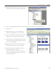
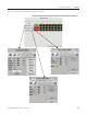
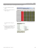
Table Of Contents
- Front Cover
- Important User Information
- Where to Start
- Table of Contents
- Preface
- Chapter 1
- Chapter 2
- System Layout and Wiring
- Before You Begin
- What You Need
- Follow These Steps
- Planning Your ArmorStart Panel Layout and Wiring
- Wiring Your ArmorStart Controllers
- Connecting the DeviceNet ArmorConnect to Your ArmorStart Device
- AC Supply Considerations for Bulletin 284 Units
- Group Motor Installations For North American and Canadian Markets
- Cabling and Installation Guidelines
- DeviceNet Network Installation
- Electromagnetic Compatibility
- System Layout and Wiring
- Chapter 3
- ArmorStart DeviceNet Configuration
- Before You Begin
- What You Need
- Follow These Steps
- Open an Existing Project in RSLogix 5000 Software
- Configure the DeviceNet Network by Using RSNetWorx Software
- Add a Scanner Module to Your ControlLogix Project
- Generate ArmorStart Tags by Using the Tag Generator Tool
- Download Controller File and Test ArmorStart Tags
- ArmorStart DeviceNet Configuration
- Chapter 4
- Chapter 5
- Faceplate Logix Integration
- Before You Begin
- What You Need
- Follow These Steps
- Import the ArmorStart Add-On Instructions
- Reassign Add-On Instruction Input and Output Parameter Data Types
- Modify ArmorStart Add-On Instruction for Equipment Status Faceplate
- Integrate ArmorStart AOI into Your Application Program Routines
- Integrate Your ArmorStart Device Application
- Add Alarm Logic for Alarm History Faceplate
- Download the Project
- Faceplate Logix Integration
- Chapter 6
- Chapter 7
- ArmorStart System Application Guide
- Before You Begin
- What You Need
- ArmorStart System Overview Display
- ArmorStart Device Faceplate Overview
- ArmorStart Device Faceplate - Fault Indication View
- Last Fault, Fault Description, and Fault Action
- ArmorStart Device Faceplate - Configuration Status View
- ArmorStart Device Faceplate - Trending View
- ArmorStart Device Faceplate - Online Help Options
- ArmorStart System Application Guide
- Appendix A
- Logix Communication and Controller Configuration
- Configuring PC Communication
- Configure the EtherNet/IP Driver
- Load the Controller Firmware Serially
- Assign IP Addresses
- Ethernet Module Firmware Update Using ControlFLASH Utility
- Browse the EtherNet/IP Network Devices
- Load the Controller Firmware
- Create a New Project File in RSLogix 5000 Software
- Configure Your Ethernet Module
- Logix Communication and Controller Configuration
- Appendix B
- Appendix C
- Back Cover/Rockwell Support

124 Publication IASIMP-QS015C-EN-P - August 2011
Chapter 6 FactoryTalk View Integration
Add Equipment Status Faceplate
The ME Equipment Status Faceplate files let you quickly load and configure a summary display of
preconfigured status and diagnostic displays or faceplates for FactoryTalk View Machine Edition. The
Equipment Status Faceplate works in conjunction with individual device faceplates and provides a single
summary display of all the faceplates that may be configured for an application. You can configure up to nine
device faceplates to run with the Equipment Status faceplate and you can launch each device faceplate
directly from it.
This example shows the Equipment Status Faceplate that you can add to your specific hardware system
display. This faceplate is configured for three rows or three devices and provides overall status of the device,
up to four additional status values to be monitored, and can launch the individual device faceplates for more
detailed information.
TIP
This section is optional and necessary only if you intend to use the Equipment Status Faceplate. To skip this
section, go to Add Alarm History Faceplate
on page 133.
IMPORTANT
In order to use the Equipment Status faceplate into your application, you must have PanelView Plus
terminal that supports 800x600 window size.