
Instruction Manual
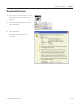

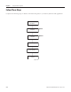
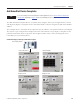
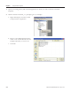
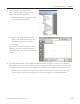
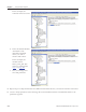
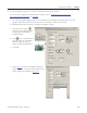
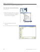
Table Of Contents
- Front Cover
- Important User Information
- Where to Start
- Table of Contents
- Preface
- Chapter 1
- Chapter 2
- System Layout and Wiring
- Before You Begin
- What You Need
- Follow These Steps
- Planning Your ArmorStart Panel Layout and Wiring
- Wiring Your ArmorStart Controllers
- Connecting the DeviceNet ArmorConnect to Your ArmorStart Device
- AC Supply Considerations for Bulletin 284 Units
- Group Motor Installations For North American and Canadian Markets
- Cabling and Installation Guidelines
- DeviceNet Network Installation
- Electromagnetic Compatibility
- System Layout and Wiring
- Chapter 3
- ArmorStart DeviceNet Configuration
- Before You Begin
- What You Need
- Follow These Steps
- Open an Existing Project in RSLogix 5000 Software
- Configure the DeviceNet Network by Using RSNetWorx Software
- Add a Scanner Module to Your ControlLogix Project
- Generate ArmorStart Tags by Using the Tag Generator Tool
- Download Controller File and Test ArmorStart Tags
- ArmorStart DeviceNet Configuration
- Chapter 4
- Chapter 5
- Faceplate Logix Integration
- Before You Begin
- What You Need
- Follow These Steps
- Import the ArmorStart Add-On Instructions
- Reassign Add-On Instruction Input and Output Parameter Data Types
- Modify ArmorStart Add-On Instruction for Equipment Status Faceplate
- Integrate ArmorStart AOI into Your Application Program Routines
- Integrate Your ArmorStart Device Application
- Add Alarm Logic for Alarm History Faceplate
- Download the Project
- Faceplate Logix Integration
- Chapter 6
- Chapter 7
- ArmorStart System Application Guide
- Before You Begin
- What You Need
- ArmorStart System Overview Display
- ArmorStart Device Faceplate Overview
- ArmorStart Device Faceplate - Fault Indication View
- Last Fault, Fault Description, and Fault Action
- ArmorStart Device Faceplate - Configuration Status View
- ArmorStart Device Faceplate - Trending View
- ArmorStart Device Faceplate - Online Help Options
- ArmorStart System Application Guide
- Appendix A
- Logix Communication and Controller Configuration
- Configuring PC Communication
- Configure the EtherNet/IP Driver
- Load the Controller Firmware Serially
- Assign IP Addresses
- Ethernet Module Firmware Update Using ControlFLASH Utility
- Browse the EtherNet/IP Network Devices
- Load the Controller Firmware
- Create a New Project File in RSLogix 5000 Software
- Configure Your Ethernet Module
- Logix Communication and Controller Configuration
- Appendix B
- Appendix C
- Back Cover/Rockwell Support
Publication IASIMP-QS015C-EN-P - August 2011 119
FactoryTalk View Integration Chapter 6
7. Create the display navigation to open the ArmorStart Faceplate at runtime.
To use the pre-configured ArmorStart Goto buttons, refer to Configuration Steps for Using
Pre-configured Goto Buttons on page 120.
a. On a desired graphic display, create a new transparent Goto display navigation button over the
graphic object that represents the motor/drive you intend to monitor and control.
b. Double-click the Goto button to configure its Display settings.
c. Click the browse button
along side of the Display field
and assign the ArmorStart
faceplate display.
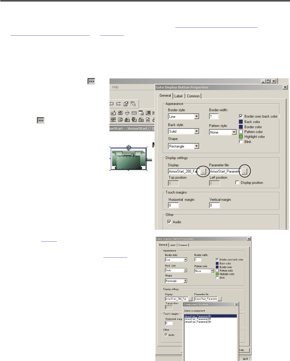
d. Click next to the Parameter
file and assign the ArmorStart
parameter file you created
earlier for this intended device.
e. Click OK.
f. Repeat step 7 for the Goto Display navigation
buttons for each of your devices and skip to Set
Initial Application Graphic on page 123
.