
Instruction Manual
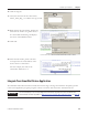

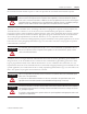


Table Of Contents
- Front Cover
- Important User Information
- Where to Start
- Table of Contents
- Preface
- Chapter 1
- Chapter 2
- System Layout and Wiring
- Before You Begin
- What You Need
- Follow These Steps
- Planning Your ArmorStart Panel Layout and Wiring
- Wiring Your ArmorStart Controllers
- Connecting the DeviceNet ArmorConnect to Your ArmorStart Device
- AC Supply Considerations for Bulletin 284 Units
- Group Motor Installations For North American and Canadian Markets
- Cabling and Installation Guidelines
- DeviceNet Network Installation
- Electromagnetic Compatibility
- System Layout and Wiring
- Chapter 3
- ArmorStart DeviceNet Configuration
- Before You Begin
- What You Need
- Follow These Steps
- Open an Existing Project in RSLogix 5000 Software
- Configure the DeviceNet Network by Using RSNetWorx Software
- Add a Scanner Module to Your ControlLogix Project
- Generate ArmorStart Tags by Using the Tag Generator Tool
- Download Controller File and Test ArmorStart Tags
- ArmorStart DeviceNet Configuration
- Chapter 4
- Chapter 5
- Faceplate Logix Integration
- Before You Begin
- What You Need
- Follow These Steps
- Import the ArmorStart Add-On Instructions
- Reassign Add-On Instruction Input and Output Parameter Data Types
- Modify ArmorStart Add-On Instruction for Equipment Status Faceplate
- Integrate ArmorStart AOI into Your Application Program Routines
- Integrate Your ArmorStart Device Application
- Add Alarm Logic for Alarm History Faceplate
- Download the Project
- Faceplate Logix Integration
- Chapter 6
- Chapter 7
- ArmorStart System Application Guide
- Before You Begin
- What You Need
- ArmorStart System Overview Display
- ArmorStart Device Faceplate Overview
- ArmorStart Device Faceplate - Fault Indication View
- Last Fault, Fault Description, and Fault Action
- ArmorStart Device Faceplate - Configuration Status View
- ArmorStart Device Faceplate - Trending View
- ArmorStart Device Faceplate - Online Help Options
- ArmorStart System Application Guide
- Appendix A
- Logix Communication and Controller Configuration
- Configuring PC Communication
- Configure the EtherNet/IP Driver
- Load the Controller Firmware Serially
- Assign IP Addresses
- Ethernet Module Firmware Update Using ControlFLASH Utility
- Browse the EtherNet/IP Network Devices
- Load the Controller Firmware
- Create a New Project File in RSLogix 5000 Software
- Configure Your Ethernet Module
- Logix Communication and Controller Configuration
- Appendix B
- Appendix C
- Back Cover/Rockwell Support
102 Publication IASIMP-QS015C-EN-P
Chapter 5 Faceplate Logix Integration
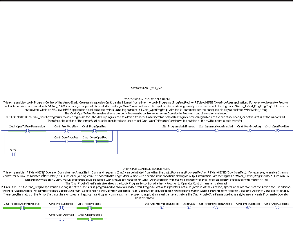
Understanding Operator Control and Program Control Transfer Logic
The first three rungs of each Add-On Instruction file handle the transfer of control from the Logix program
(program control) to the faceplate (operator control). It is important that you understand how the two
operator control rungs (shown below) operate so you achieve the program-to-operator and
operator-to-program control transfers.
Two Operator Rungs
In this example, the rungs enable operator control of the intended ArmorStart device. You can initiate
Command requests (Cmd) from either the Logix Programs (ProgOperReq) or FactoryTalk View ME
ArmorStart Faceplate (OperOperReq).
Enabling Operator Control of Drive
To enable operator control for an ArmorStart associated with Motor_with_284 AOI instance, you could add
a rung to the Logix MainRoutine with specific input conditions driving an output instruction with the tag
name Motor_with_284.Cmd_ProgOperReq. Likewise, you could add a push button within a FactoryTalk
View ME/SE Faceplate with a value tag name of #1.Cmd_OperOperReq with the #1 parameter for that
faceplate display associated with Motor_with_284.
A Motor_with_284.Cmd_ProgToOperPermissive tag must also be included in the Logix program to control
whether program-to-operator control transfer requests are allowed or acted upon. A tag value of 1 permits