Quick Start On-Machine ArmorStart Accelerator Toolkit Catalog Numbers 280D, 281D, 283D, 284D
Important User Information Solid-state equipment has operational characteristics differing from those of electromechanical equipment. Safety Guidelines for the Application, Installation and Maintenance of Solid State Controls (publication SGI-1.1 available from your local Rockwell Automation sales office or online at http://www.rockwellautomation.com/literature/) describes some important differences between solid-state equipment and hard-wired electromechanical devices.
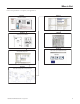
Where to Start Follow the path below to complete your application.
Where to Start Notes: 4 Publication IASIMP-QS015C-EN-P - August 2011
Table of Contents Preface About This Publication . . . . . . . . . . . . . . . . . . . . . . . . . . . . . . . . . . . . . . 9 Required Software . . . . . . . . . . . . . . . . . . . . . . . . . . . . . . . . . . . . . . . . . 10 Conventions . . . . . . . . . . . . . . . . . . . . . . . . . . . . . . . . . . . . . . . . . . . . . . 10 Additional Resources . . . . . . . . . . . . . . . . . . . . . . . . . . . . . . . . . . . . . . . 11 Chapter 1 Hardware Selection Before You Begin. . . . . . . . . . . . .
Table of Contents Electromagnetic Compatibility . . . . . . . . . . . . . . . . . . . . . . . . . . . . . . . 56 General Notes for Bulletin 284 Devices. . . . . . . . . . . . . . . . . . . . . 56 Ground the ArmorStart Controller. . . . . . . . . . . . . . . . . . . . . . . . . 56 Chapter 3 ArmorStart DeviceNet Configuration Before You Begin. . . . . . . . . . . . . . . . . . . . . . . . . . . . . . . . . . . . . . . . . . 57 What You Need . . . . . . . . . . . . . . . . . . . . . . . . . . . . . . . . .
Table of Contents Add Alarm Logic for Alarm History Faceplate . . . . . . . . . . . . . . . . . 109 Download the Project . . . . . . . . . . . . . . . . . . . . . . . . . . . . . . . . . . . . . 111 Chapter 6 FactoryTalk View Integration Before You Begin. . . . . . . . . . . . . . . . . . . . . . . . . . . . . . . . . . . . . . . . . 113 What You Need . . . . . . . . . . . . . . . . . . . . . . . . . . . . . . . . . . . . . . . . . . 113 Follow These Steps . . . . . . . . . . . . . . . . . . . . . . . .
Table of Contents Load the Controller Firmware. . . . . . . . . . . . . . . . . . . . . . . . . . . . . . . 168 Create a New Project File in RSLogix 5000 Software . . . . . . . . . . . . 170 Configure Your Ethernet Module . . . . . . . . . . . . . . . . . . . . . . . . . . . . 171 Appendix B FactoryTalk View Application Configuration Create New FactoryTalk View Application . . . . . . . . . . . . . . . . . . . . 173 Create Design (local) and Runtime (target) Shortcuts . . . . . . . . . . . .
Preface About This Publication This quick start provides step-by-step instructions for using the ArmorStart Accelerator Toolkit to help you easily design, install, operate, and maintain an on-machine system. Included are pre-configured files, selection tools, and examples of using a Logix controller to connect to multiple devices (ArmorStart distributed motor controllers and HMI terminal) over the EtherNet/IP and DeviceNet network to provide Intelligent Motor Control for your application requirements.
Preface Required Software To complete this quick start, the following software is required. Rockwell Automation Software Cat. No. Version Required for RSLogix 5000 • ControlFlash • BOOTP/DHCP utility (EtherNet/IP) • RSLinx Classic 9324-RLD300RNE 17 or later All EtherNet/IP and ControlLogix processors FactoryTalk View Studio for Machine Edition • FactoryTalk Services • RSLinx Enterprise • RSLinx Classic 9701-VWSTMENE 5.
Preface Additional Resources The following documents contain additional information concerning related Rockwell Automation products. Resource Description ArmorStart Distributed Motor Controller User Manual, publication 280-UM002. Provides mounting and wiring instructions for the 280, 281, 283, and 284 ArmorStart controllers. It also provides information on how to set parameters and troubleshoot the AmorStart controller. DeviceLogix System User Manual, publication RA-UM003.
Preface Notes: 12 Publication IASIMP-QS015C-EN-P - August 2011
Chapter 1 Hardware Selection In this chapter, you will select six ArmorStart controllers including peripherals by using the Rockwell Automation Integrated Architecture Builder (IAB) software. This graphical software tool is used to configure Logix-based automation systems. IAB helps you select hardware and generate a bill of material (BOM) for applications that include I/O, networks, ArmorStart controllers, On-Machine cabling, wiring, and other devices. Outputs include BOM and reports with graphics.
Chapter 1 Hardware Selection Follow These Steps Complete the following steps to select your system hardware.
Hardware Selection Chapter 1 Select an ArmorConnect Power Media System Follow these steps to select an ArmorConnect power media system by using Integrated Architecture Builder (IAB) software. 1. Open the Integrated Architecture Builder software. 2. Click ‘I want to create a New project.’ and click OK. 3. Click Integrated Architecture Workspace. 4. Enter a Workspace Name. 5. Click OK. 6. Select ControlLogix Subsystem. 7. Click OK.
Chapter 1 Hardware Selection The ControlLogix Chassis Preference dialog box appears. 8. Select the appropriate settings. For this example, 4 is the preferred size. 9. Click Next until the Networks dialog box appears. 10. Enter the number of EtherNet/IP and DeviceNet networks. For this example, enter 1 for EtherNet/IP and 1 for DeviceNet. 11. Click Next. 12. Check ‘Click here to manually choose Logix processor(s)’. 13. Select 1756-L63 as the processor. 14. Click Finish.
Hardware Selection Chapter 1 15. When finished configuring the chassis, click the Hardware tab to view the configured chassis.
Chapter 1 Hardware Selection Adding a Three-phase Power Network and a Branch You will now add a three-phase power network and a branch, add devices to a branch, configure the devices and accessories for the device. Add a Three-phase Power Network 1. Click the new network icon on the toolbar at the top of the screen. 2. Select 3PhasePwr and click OK. 3. Enter a new network name. 4. Click OK. 5. From the Line Voltage pull-down menu, choose 480V 60Hz.
Hardware Selection Chapter 1 6. From the Control Voltage pull-down menu, choose 24VDC. This will be the default control voltage for ArmorStart motor controllers connected to the network. Other options are 120V AC and 240V AC. Control voltage might be distributed by a Control Power network, which you can also configure in the IAB software. A new three-phase power network is created with a single branch and displayed in the network view.
Chapter 1 Hardware Selection Add Device to a Branch (Three-phase Power Network) Follow these steps to add a device to a branch of a three-phase power network. 1. Click the 3 Phase tab. 2. Under Motor Controller, select Distributed Starters. A list of ArmorStart motor controllers appear. 3. Select the desired ArmorStart device and drag it over the Branch_0 line. In this example, select the 283D ArmorStart. When the plus sign appears, release the left mouse button.
Hardware Selection Chapter 1 For example, when you select Horsepower, the horsepower options appear on the right. 5. Choose the appropriate horsepower amount. 6. Choose other options as appropriate. After choosing all of your appropriate options, the dialog box should look similar to this.
Chapter 1 Hardware Selection Configure Device Accessories Follow these steps to configure the device accessories. You will need to add one input and two output cables for the photoelectric sensor and stack lights respectively that will be added later to the BOM in ProposalWorks. 1. Click Output Cable Port #1. 2. Make the following selections. a. Select Cable Type under the First Cable Type Selection b. Under Cable Type, choose ‘Cordset-Male’. 3.
Hardware Selection Chapter 1 4. Click Accept in the upper left when you are finished selecting the cordset. 5. Continue to click Accept until you are at the ArmorStart configuration assistant to complete the accessories configuration.
Chapter 1 Hardware Selection 6. Copy the configuration from Port #1 to Output Cable Port #2 as shown. 7. Select NO SELECTION for Output Cable Port #2. 8. Click Accept. 9. Once the output cables have been configured, click Input Cable Port #1 to configure the port cable.
Hardware Selection Chapter 1 10. Click Cable Type, then Patchcord. 11. Click the ‘?’ next to Patchcord. 12. Make the following selections as shown.
Chapter 1 Hardware Selection 13. Select NO SELECTION under the second cable type. 14. Select No Cable on the right. 15. Click Accept until you have exited the RAISE configurator and are back in the network view. 16. Double-click the Starter.
Hardware Selection Chapter 1 17. Change the name and click OK. The completed configuration for the 283D ArmorStart will look like this. Repeat the procedures starting on page 20 to add additional devices to the branch, configure the devices, and select accessories.
Chapter 1 Hardware Selection The completed configuration for the 281D should look similar to this. The completed configuration for the 284D ArmorStart should look similar to this.
Hardware Selection Chapter 1 View and Configure Network After completing the configuration sequence, the network view appears. 1. Click Run Wizard. 2. From the various pull-down menus and fields, choose the appropriate values. 3. Click OK.
Chapter 1 Hardware Selection 4. Click the arrow. 5. Check the appropriate parameters for your application. Add a Control Power Network 1. Click the New Network icon. 2. Select the ControlPwr network. 3. Click OK. . 4. Enter your network name then click OK. The IAB creates a new control power network and displays the network voltage under the power distribution panel at the left end of the network. Notice the tab added to the network view for the Lab control Power network.
Hardware Selection Chapter 1 5. Add the current ArmorStart devices on the three-phase network to the control network. a. Click the hardware tab. b. Click the first ArmorStart device and right-click the icon of the ArmorStart device. c. Choose ‘Connect channel...to Network1:’ Control power Armorstart’’. The names of the ArmorStart devices may be different. 6. Repeat step 5 for all of the ArmorStart devices listed under the hardware tab. 7. Click the network tab. 8. Select the Network view.
Chapter 1 Hardware Selection 10. From the various pull-down menus and fields, choose the appropriate values. 11. Click OK. 12. Click the arrow. 13. Check the appropriate parameters for your application. Add a DeviceNet Network Follow these steps to add a DeviceNet network. 1. Click the New Network icon. 2. Click OK.
Hardware Selection Chapter 1 3. Enter the network name. 4. Select the power supply. 5. Click OK. 6. Repeat the process to add the ArmorStart devices to the control power network, but instead select ‘Connect channel’.’to Network1:’DeviceNet ArmorStart. 7. Click the arrow. 8. Check the appropriate parameters for your application.
Chapter 1 Hardware Selection Export the IAB Configuration to ProposalWorks Follow these steps to export the IAB configuration to ProposalWorks. 1. From the File menu, choose Export to ProposalWorks File. 2. Enter a file name for the exports. 3. From the Files of Type pull-down menu, choose ProposalWorks Files (*prp). 4. Click Open. 5. Click Yes or No to export the IAB project to ProposalWorks and add components to the BOM.
Hardware Selection Chapter 1 Once the validation process has completed, the following dialog box appears. 6. Click OK. The ProposalWorks file created (ArmorStart BOM) is now on the respective directory. 7. Open Proposal Works. 8. From the File menu, choose Open. 9. Select ArmorStart BOM, then click Open. 10. Click Yes. Your project is saved. If you click No, the project is not saved.
Chapter 1 Hardware Selection 11. Enter a file name, then click Save. The default is the name selected in step 2. 12. Open the ArmorStart BOM and review the bill of material generated by the IAB.
Hardware Selection Chapter 1 Add Additional Equipment and Generate a Complete BOM 1. Verify that the Integrated Architecture Builder is open in ProposalWorks. TIP Please note, this is an example of optional parts. Add or remove items as needed. Prices listed are subject to change. 2. Add the following items that will complete the BOM for this application. The BOM is complete. It can be reviewed in ProposalWorks, converted to a spreadsheet, or made into a proposal in a Microsoft Word document. 3.
Chapter 1 Hardware Selection This example is a partial equipment list. The prices listed are subject to change.
Chapter 2 System Layout and Wiring In this chapter, you plan the panel layout and wiring for your ArmorStart system. You can use the AutoCAD Electrical drawings supplied on the ArmorStart Accelerator Toolkit CD to add or remove components to and from your ArmorStart system. Before You Begin Complete your system hardware selection (refer to Chapter 1). What You Need • ArmorStart Accelerator Toolkit CD, publication IASIMP-SP015.
Chapter 2 System Layout and Wiring Follow These Steps Complete the following steps to plan your system layout and wiring.
System Layout and Wiring Chapter 2 Planning Your ArmorStart Panel Layout and Wiring The toolkit includes AutoCAD Electrical DWG project files that include panel layout and wiring diagrams that you can easily modify for your specific application. Individual DXF, and PDF files are also available for use in standard AutoCAD and non-AutoCAD drawing and image software packages. The diagrams include power and control wiring examples. The ArmorStart controllers are connected with ArmorStart media.
Chapter 2 System Layout and Wiring Panel Layout Diagrams The AutoCAD Electrical project includes several panel-layout diagrams (with BOM) based on the ArmorStart distributed motor controllers. Choose an appropriate diagram as a starting point. Add or remove components as needed. The example shows a control panel with a ControlLogix controller, PanelView display, and stack lights as well as control power components.
System Layout and Wiring Chapter 2 Sample Bill of Material Publication IASIMP-QS015C-EN-P - August 2011 43
Chapter 2 System Layout and Wiring ArmorStart Distributed Motor Controllers Wiring Diagrams The AutoCAD Electrical project includes a variety of ArmorStart wiring diagrams. The drawing titles indicate ArmorStart controller types. Add or remove components and drawings as needed. This example shows power wiring for an ArmorStart 284D device and other power components.
System Layout and Wiring Chapter 2 Access Other Allen-Bradley CAD Drawings Follow these steps to download other Allen-Bradley product CAD drawings. 1. Open your browser and go to http://ab.com/e-tools. The Configuration and Selection Tools web page opens. TIP If you know the complete catalog number of your Allen-Bradley product, you can enter it here and click Submit. However, you need a complete catalog number string to get the configuration results. 2.
Chapter 2 System Layout and Wiring Wiring Your ArmorStart Controllers This section provides information pertaining to wiring your ArmorStart distributive motor controller. General Precautions ATTENTION ATTENTION ATTENTION The controller contains electrostatic discharge (ESD) sensitive parts and assemblies. Static control precautions are required when installing, testing, servicing, or repairing the assembly. Component damage may result if the ESD control procedures are not followed.
System Layout and Wiring Chapter 2 ArmorStart Device Wiring Wiring in an industrial control application can be divided into three groups; power, control, and signal. Follow these recommendations for physical separation between these to reduce the coupling effect: • Minimum spacing between different wire groups in the same tray should be 16 cm (6 in.). • Run wire outside an enclosure conduit or have shielding or armor with equivalent attenuation. • Run different wire groups in separate conduits.
Chapter 2 System Layout and Wiring The following illustrations and table provide various terminal designations.
System Layout and Wiring Chapter 2 Bulletin 284 ArmorStart Power and Control Terminals Power, Control, Safety Monitor, and Ground Terminal Designations Terminal Designation SM11 1 Description Safety monitor input SM21 Safety monitor input A1(+) Control power input A2(-) Control power common PE Ground 1/L1 Line power phase A 3/L2 Line power phase B 5/L3 Line power phase C Only available with the Safety Monitor option.
Chapter 2 System Layout and Wiring Connecting the DeviceNet ArmorConnect to Your ArmorStart Device The ArmorConnect power media offers both three-phase and control power cable system of cord sets, patch cords, receptacles, tees, reducers, and accessories for use with the ArmorStart distributed motor controller. These cable system components allow quick connection of ArmorStart distributed motor controllers, reducing installation time.
System Layout and Wiring Chapter 2 Control Power Media System Overview Enclosure PLC Bulletin 1492FB Branch Circuit Protective Device 1606-XLSDNET4 DeviceNet Power Supply Bulletin 1606 Power Supply Bulletin 280/281 ArmorStart Bulletin 283 ArmorStart Bulletin 284 ArmorStart RESET OFF Bulletin 800F Emergency Stop Pushbutton ID Cat. No. Description 6 889N-F65GFNM-x1 Control power media patchcords - Patchcord cable with integral female or male connector on each end.
Chapter 2 System Layout and Wiring Cord Grips for ArmorStart Devices with 10 A Short-circuit Protection Rating 1 in. Lock Nut 3/4 in. Lock Nut Thomas & Betts Cord Grip Part Number 2931NM 3/4 in. Stain Relief Cord Connector 0.78...1.42 cm (0.31...0.56 in.) Used with Control Power Media Cordset - Example Catalog Number 889N-M65GF-M2 Thomas & Betts Cord Grip Part Number 2940 NM 1 in. Stain Relief Cord Connector 0.78...1.42 cm (0.31...0.56 in.
System Layout and Wiring Chapter 2 AC Supply Considerations for Bulletin 284 Units This section describes AC supply considerations for Bulletin 284 units. Ungrounded and High-resistive Distribution Systems ATTENTION The Bulletin 284 device contains protective metal oxide variables (MOVs) that are referenced to ground. These devices should be disconnected if the Bulletin 284 device is installed on an ungrounded and high-resistive distribution system.
Chapter 2 System Layout and Wiring Group Motor Installations For North American and Canadian Markets The ArmorStart distributed motor controllers are listed for use with each other in group installations per NFPA 79, Electrical Standard for Industrial Machinery. When applied according to the group motor installation requirements, two or more motors, of any rating or controller type, are permitted on a single branch circuit.
System Layout and Wiring Chapter 2 Since the ArmorStart device is available with a factory installed HOA keypad option, this may require the ArmorStart device to be selected and installed as follows. If the application requires frequent use of the hand-operated interface by the equipment operator: • they should not be less than 0.6 m (2 ft) above the servicing level and are within easy reach of the normal working position of the operator.
Chapter 2 System Layout and Wiring Electromagnetic Compatibility The following guidelines are provided for EMC installation compliance. General Notes for Bulletin 284 Devices • The motor cable should be kept as short as possible to avoid electromagnetic emission as well as capacitive currents • Conformity of the device with CE EMC requirements does not guarantee an entire machine installation complies with CE EMC requirements. Many factors can influence total machine and installation compliance.
Chapter 3 ArmorStart DeviceNet Configuration In this chapter, you will configure your ArmorStart device by using RSNetWorx for DeviceNet software, RSLogix 5000 software, and the DeviceNet Tag Generator Tool. This significantly simplifies ArmorStart device configuration. Appendix A on page 155, includes the setup procedures for your personal computer and Logix communication. These procedures apply only if you are creating a new project file in RSLogix 5000 software.
Chapter 3 ArmorStart DeviceNet Configuration Follow These Steps Complete the following steps to configure your ArmorStart device.
ArmorStart DeviceNet Configuration Chapter 3 Open an Existing Project in RSLogix 5000 Software IMPORTANT If you are creating a new project and have not configured your personal computer communication or controller hardware, refer to Appendix A on page 155. 1. Launch RSLogix 5000 software. 2. Select Open Project. The Open/Import Project dialog box opens. 3. Browse to your controller file. 4. Click Open.
Chapter 3 ArmorStart DeviceNet Configuration Configure the DeviceNet Network by Using RSNetWorx Software 1. Refer to Chapter 2 for wiring the ArmorStart devices and the DeviceNet scanner module on the DeviceNet network. Make sure that the devices are powered. 2. Launch RSNetWorx for DeviceNet software. 3. From the File menu, choose New. 4. Click the Online icon. The network browser dialog box appears. This is where you select the Ethernet driver where the controller resides. 5.
ArmorStart DeviceNet Configuration Chapter 3 6. Select the DeviceNet network. 7. Click OK. Online devices on the selected DeviceNet network for the specific node address are displayed. TIP An electronic data sheet (EDS) file for each device should be loaded for each device type on the network. If there is a red question mark on the device, or the following message appears, you can download it from the Rockwell Automation website http://www.ab.com/networks/eds.
Chapter 3 ArmorStart DeviceNet Configuration 8. Double-click the ArmorStart device on a specific node address. a. Upload the devices properties if they have not been yet. b. Click Parameters on the device properties tab. c. For the ArmorStart 280D and 281D device, make sure the consumed IO Assy is 160 and the Produce IO Assy is 161. d. Change any other parameter as needed for your specific application. e.
ArmorStart DeviceNet Configuration Chapter 3 9. If the Consumed IO Assy or any other parameter needs to be changed: a. Click the current value. b. Type in the appropriate value. c. Click Apply. Some parameters have predefined values you can select versus typing in a value. d. Click OK. The icon signifies a read-only parameter that cannot be configured.
Chapter 3 ArmorStart DeviceNet Configuration 10. Once you have browsed all of the nodes (63 total nodes on the DeviceNet network), right-click the scanner icon (the 1756-DNB icon), and choose Upload from Device. 11. Double-click the scanner icon. a. Enter a new name for the scanner or accept the default name. b. Make sure that the node address corresponds to the node on which the scanner is commissioned. c. Click OK. 12. Click the Scanlist tab. a.
ArmorStart DeviceNet Configuration Chapter 3 14. Save the .dnt file. Add a Scanner Module to Your ControlLogix Project Follow these steps to add and configure a DeviceNet scanner module to the controller. 1. In the RSLogix software, right-click I/O Configuration on the Controller Organizer window and select New Module. The Select Module dialog box appears.
Chapter 3 ArmorStart DeviceNet Configuration 2. Expand the Communications tree and select 1756-DNB. 3. Click OK. 4. In the New Modules dialog, enter the module name. 5. Choose the node number and slot number of where the DeviceNet module resides in the controller backplane. 6. Click OK twice. A DeviceNet I/O module is added to the I/O configuration tree.
ArmorStart DeviceNet Configuration Chapter 3 Generate ArmorStart Tags by Using the Tag Generator Tool Follow these steps to generate ArmorStart device tags. TIP Make sure RSNetWorx software is closed before starting the DeviceNet Tag Generator Tool. 1. Launch the DeviceNet Tag Generator tool. 2. Select the RSLogix 5000 Project where tags need to be added. 3. Click Select Scanner and select the DeviceNet scanner module that was added in the previous section.
Chapter 3 ArmorStart DeviceNet Configuration 4. Click Select RSNetWorx and select the .dnt file that was saved from page 65. 5. Click Select Scanner Node and then select the appropriate scanner node. 6. Click Generate Tags on the right side of the dialog box and then click the Generate Tags tab. 7. Close the Tag Generator tool after the tags are generated.
ArmorStart DeviceNet Configuration Chapter 3 Download Controller File and Test ArmorStart Tags Verify Tags 1. Go to the RSLogix 5000 editor and double-click Controller tags from the Controller Organizer window. You’ll see generated input and output tags for all of the devices that were added to the scanlist. For example, the tag name Dnet_ArmorStart_Module_N04_POL _I is for input tags for an ArmorStart device located at node address 4.
Chapter 3 ArmorStart DeviceNet Configuration These the tags that correspond to the parameters from the Consumed IO instance for the corresponding ArmorStart device. Set Project Path and Download to Controller 1. Save your changes. 2. Move the keyswitch on controller to Program. 3. Click the Who Active button.
ArmorStart DeviceNet Configuration Chapter 3 2. Expand the network tree. 3. Select your controller and click Set Project Path. EtherNet/IP If using serial communications, verify that the 1756-CP3 cable is connected between the computer and the controller. Serial 4. Click Download. 5. Click Download. The project Path updates. EtherNet/IP Serial 6. Move the keyswitch on controller to Run.
Chapter 3 ArmorStart DeviceNet Configuration Device Tag Test Setup The tags used in this test procedure apply to the ArmorStart 284D device. The tags for the other ArmorStart devices are different. IMPORTANT Before you begin the test, make sure the DeviceNet Scanner Module (DNBT) on the controller is set to Run. Follow these steps to make sure the scanner is in Run mode. 1. Double-click Controller Tags, then click Show in the Controller Tag dialog box on the right. 2.
ArmorStart DeviceNet Configuration Chapter 3 4. Make sure the controller tags are in ‘Monitor Tags’ mode and not ‘Edit Tags’ mode by checking the tab field at the bottom. 5. Expand the Local:1:0 (output tags) and within it, expand the Local:1:0.CommandRegister tag as shown. 6. Locate the Local:1:0.CommandRegister.Run value and if set to 0, change value to 1. 7. Check the DeviceNet scanner module on the controller and it should read ‘Run’ on it. Test Procedure 1. Place the keyswitch in the Run position.
Chapter 3 ArmorStart DeviceNet Configuration 3. From the Monitor Tags tab, locate and expand the ArmorStart 284D output tags. Follow this procedure if you need to change the value of a tag in RSLogix software. a. Select the tag value. b. Enter or select the desire value. c. Press Enter. 4. Change the FaultReset tag to 1 and press Enter to clear any initial faults. 5. Change FaultReset back to 0 and press enter. 6. Verify that the I.Status_ready tag value is 1, indicating that the device is ready. 7.
Chapter 4 ArmorStart Local Control Configuration In this chapter, you will configure your ArmorStart device for standalone or device level control. DeviceLogix devices have built-in processing capabilities that include controlled shutdowns in the event of network loss, or a controlled continuation of the process. It reduces the sense-to-actuation time, resulting in higher performance and simpler programming. Before You Begin • Complete your system hardware selection (refer to Chapter 1).
Chapter 4 ArmorStart Local Control Configuration Follow These Steps Complete the following steps to configure your ArmorStart devices for stand-alone Devicelogix applications.
ArmorStart Local Control Configuration Chapter 4 Create a DeviceLogix Program on an ArmorStart Device Configuring DeviceLogix smart components for local control can be accomplished with RSNetWorx for DeviceNet software. With this software, you can set up DeviceNet components for system installation or field maintenance through the use of pull-down menus and dialog boxes. DeviceLogix enabled products can also be created and monitored using the 193-DNCT device.
Chapter 4 ArmorStart Local Control Configuration 6. Click Start Logix Editor. 7. If the DeviceLogix Editor Style dialog box appears, select function Block Editor. 8. Click OK. You are now ready to begin building your logic program. Build Your Logic Program Follow these steps to build your logic program. 1. In the Logic editor, click the edit icon to enter the Edit mode. 2. Click Yes to enter Edit mode.
ArmorStart Local Control Configuration Chapter 4 When in Edit mode, the following buttons appear for use in creating the logic program. 3. Drag the Bit Input icon from the Timer/Counter or Move/Logical tab to the grid. 4. Double-click the tag and then click the down arrow. 5. Click the ‘+’ next to Network Boolean. 6. Double-click Net Input 0. 7. Repeat steps 3 and 4 then click the ‘+’ next to Hardware Boolean Input. 8. From the Hardware Boolean Input, select Input0.
Chapter 4 ArmorStart Local Control Configuration 9. Click the Move/Logical tab. 10. Drag the BAND tag to the grid. 11. Drag the Net Input0 connection point to the In1 connection point. 12. Click In1 again to make the connection. The line will remain indicating that the connection is made. 13. Repeat steps 10 to 12 connect the IO Input0 tab to the In2 connection point. 14. Click and hold the Bit Output tab on the toolbar. 15. Drag the BAND function block to the left. 16.
ArmorStart Local Control Configuration Chapter 4 17. Click the down arrow. 18. Click the ‘+’ next to Hardware Boolean. 19. Double-click Run Fwd. 20. Connect the BAND block to the Run Fwd tag. 21. From the Edit pull-down menu, choose Recovery Mode. 22. Click Enabled. 23. Click OK. 24. Click the Logic Verify icon on the toolbar to determine if the program is valid and error-free. If the logic is valid and passed certification, the following dialog box appears. 25. Click OK.
Chapter 4 ArmorStart Local Control Configuration 26. Click the Edit mode icon to exit the editor. If the logic fails verification, the following dialog box appears. 27. Click OK. You will return to the logic editor where you can make the necessary changes and revalidate the program. Download Program to ArmorStart 1. Download the program to the ArmorStart device by choosing Download from the communication pull-down menu. 2. Click OK if the download is successful. 3.
ArmorStart Local Control Configuration Chapter 4 5. Click Apply, then OK. If the master scanner is currently scanning the ArmorStart device to which you are downloading, you must first access the DeviceNet’s scanner’s scanlist to remove the device from the scanlist. If this new logic results in different connection sizes, adjust the master scanner as follows: a. Put the master in Idle mode. This may mean turning a processor’s key switch to PROG. b.
Chapter 4 ArmorStart Local Control Configuration DeviceLogix Programming Example This example is a combination of different modes that can be used together in an application for the 284D ArmorStart device. A logic controller ladder logic program is controlling the ArmorStart device (auto control). In the event of an I/O connection fault, the external push buttons (manual control) will be allowed to control the ArmorStart and local I/O.
ArmorStart Local Control Configuration Chapter 4 Network Input 0 Logic If there is an IO Connection fault, manual operation from a pendant station or other push buttons will be allowed. In this example, input 1 of the Boolean OR gate is used for the PLC control. In manual control, input 0 could be from a sensor on a conveyor belt in which after manually starting the conveyor using a pendant station, the product will pass the sensor.
Chapter 4 ArmorStart Local Control Configuration The DeviceLogix program can also be created to prevent unwanted automatic restarts after clearing a fault.
ArmorStart Local Control Configuration Chapter 4 Here is a list of hardware inputs and status inputs that can be used in the DeviceLogix program with the ArmorStart device.
Chapter 4 ArmorStart Local Control Configuration Notes: 88 Publication IASIMP-QS015C-EN-P - August 2011
Chapter 5 Faceplate Logix Integration In this chapter you import pre-configured logic, referred to as an Add-On Instruction (AOI), into your RSLogix 5000 application that integrates your ArmorStart device configuration with the ArmorStart faceplate. This chapter also provides instructions on how to configure the Add-On Instruction to work with the Equipment Status and ME Alarm History faceplates and how to integrate the Add-On Instructions into your specific application logic.
Chapter 5 Faceplate Logix Integration Follow These Steps Complete the following steps to add the necessary logic to your RSLogix 5000 application for use with the ArmorStart faceplates. Import the ArmorStart Add-On Instructions page 91 Reassign Add-On Instruction Input and Output Parameter page 92 Optional Step Complete if Equipment Status faceplate is needed in application.
Faceplate Logix Integration Chapter 5 Import the ArmorStart Add-On Instructions The pre-configured ArmorStart Add-On Instructions provide the logic for the pre-configured FactoryTalk View Machine ArmorStart faceplates. These pre-configured faceplates let you monitor, control, and diagnose your ArmorStart device from a PanelView Plus terminal or Industrial Computer.
Chapter 5 Faceplate Logix Integration 5. Select the ArmorStart Add-On Instruction faceplate file appropriate for your ArmorStart service class. In this example, the ArmorStart_284_AOI file is chosen. 6. Click Import.
Faceplate Logix Integration 3. Scroll to and select the Inp_ArmorStart_xxx AOI tag and click Chapter 5 next to the Data Type field. The Select Data Type dialog box opens. 4. Browse to the Input Data Type that matches the ArmorStart type, DeviceNet node, and data type that was created when you generated tags for the device, by using the DeviceNet tag generator tool in Chapter 3. It should have a name similar to the device you configured, for example, AB_284D_FHB2P3X10_I_85284B98.
Chapter 5 Faceplate Logix Integration The Data Type field updates. This example shows an ArmorStart 284 output tag’s data type. 9. Select the Sts_DeviceNet_Scanner tag and click the browse button to display the data type field. The Select Data Type dialog box appears. 10. Browse to the status data type that matches the DNB scanner module data type that was created when you configured the scanner in Chapter 3. 11. Click OK. The Data Type field updates.
Faceplate Logix Integration Chapter 5 Modify ArmorStart Add-On Instruction for Equipment Status Faceplate TIP IMPORTANT This is an optional step and necessary only if you intend to use the Equipment Status Faceplate. To skip this step, go to Integrate ArmorStart AOI into Your Application Program Routines on page 96. To incorporate Equipment Status Faceplate into your application, make sure the PanelView Plus terminal supports 800x600 window size.
Chapter 5 Faceplate Logix Integration 2. Set the tag Inp_NumRowsVis for your ArmorStart Add-On Instruction to the number of rows that you will use on the Equipment Status Faceplate. a. Under the Add-On Instructions folder in the system tree, double-click the ArmorStart Add-On Instruction that you will use for the device in row 1. b. Under the Parameters tab, find the Inp_NumRowsVis tag and check the Vis box to make the tag visible on the AOI.
Faceplate Logix Integration Chapter 5 4. Select the ArmorStart Add-On Instruction. In this example, the ArmorStart_284_AOI file is selected. 5. Assign an ArmorStart Data Type tag to the main AOI tag with the same name of the module you want to control and monitor. In this example the tag name is Motor_with_284. 6. Right-click the tag and associate Motor_with_284 tag with the ArmorStart_284_AOI Data Type. 7.
Chapter 5 Faceplate Logix Integration 9. Enter the Inp_Scaled_Speed_At_xxxx value. The Add-On Instruction scales the drive input and output speed values based on the value entered. To access the fault codes for the ArmorStart device, you need to get an explicit message. Fault_Msg parameter is of the data type message. It needs to be connected to the Explicit Message tag already in the Add-On Instruction as shown in the example. 10. Click next to the Motor_Fault_Msg tag.
Faceplate Logix Integration Chapter 5 11. From the pull-down menus and fields, choose the appropriate settings as follows: • Message Type = CIP Generic • Service Type = Get Attribute Single • Class = 29 • Attribute = 9c • Instance = 1 12. From the Destination pull-down menu, choose Motor_With_284.Fault_Msg_code.
Chapter 5 Faceplate Logix Integration 13. Click the Communication tab. The communication properties are displayed. Notice that the Path has not been identified. 14. Click Browse to enter the path. a. Select the previous module followed by a comma. b. Enter 2 for the port of the scanner module. c. Enter the DeviceNet node address of the ArmorStart device that is communicated with, to get the fault codes. For this example, the Armorstart node address is 4.
Faceplate Logix Integration Chapter 5 16. Click the Tag tab. 17. Verify that the name in the name field is Motor_Fault_Msg_xxx which is the tag in AOI. 18. Right click on Sts_DeviceNet_Scanner tag and select the Local:1:S tag from the list. It is the module defined tag and displays the status of the DNBT scanner. 19. Click OK. 20. Enter the DeviceNet_Node value that corresponds to the node address of the device that it is connected to. For this example, the node of the ArmorStart 284 device is 4.
Chapter 5 Faceplate Logix Integration Understanding Operator Control and Program Control Transfer Logic The first three rungs of each Add-On Instruction file handle the transfer of control from the Logix program (program control) to the faceplate (operator control). It is important that you understand how the two operator control rungs (shown below) operate so you achieve the program-to-operator and operator-to-program control transfers.
Faceplate Logix Integration Chapter 5 the associated control transfer requests. A value of 0 prevents the associated control transfer requests. ATTENTION If an Xxxx.Cmd_ProgToOperPermissive tag is set to 1, the associated Add-On Instruction is programmed to allow a transfer from Program Control to Operator Control regardless of the current direction, speed, or active status of the ArmorStart device. In addition, the AOI is programmed to transfer the current Program Speed value Xxxx.
Chapter 5 Faceplate Logix Integration Add-On Instruction Program Tag Listing and Function This table provides the interface tag names and functions that are within the Add-On Instructions. You can read from and write to these tags from your specific application logic. This provides control and monitoring of your configured devices.
Faceplate Logix Integration Chapter 5 ArmorStart Status Tags Tag Names Function Corresponding ArmorStart Device Tag Sts_DriveStatus_AtReference Inp_ArmorStart_xxx.AtReference Sts_DriveStatus_Input0 Inp_ArmorStart_xxx.Input0 Sts_DriveStatus_Input1 Inp_ArmorStart_xxx.Input1 Sts_DriveStatus_Input2 Inp_ArmorStart_xxx.Input2 Sts_DriveStatus_Input3 Sts_DriveStatus_Mon Sts_DriveStatus_Ready Provides Status of Corresponding ArmorStart device Tag Inp_ArmorStart_xxx.Input3 Inp_ArmorStart_xxx.
Chapter 5 Faceplate Logix Integration Common Application Logic Examples You have the option to programmatically control the ArmorStart device via Logix software. Example rungs are shown in ArmorStart_AOI_Example_Code.acd included in the toolkit CD. • Device_xxx_RunForward_Command • Device_xxx_RunReverse_Command • Device_xxx_Reset_Command Follow these steps to add application logic to your routine. 1. Extract the ArmorStart_AOI_Example_Code.acd from the accelerator toolkit CD and save it. 2.
Faceplate Logix Integration Chapter 5 5. Select the rung you want to export and right-click the rung. 6. Choose Export Rungs. 7. Save the rung as .L5X. 8. Open your application logic file in RSLogix 5000 software. 9. Select the rung where you want to import the saved rung and right-click 10. Choose Import Rungs.
Chapter 5 Faceplate Logix Integration 11. Select Rung15_from_MainRoutine.L5x. 12. Click Import. 13. Click OK from the Import Configuration dialog box. The rung is copied into the desired location. 14. Change the tag names to what you need. 15. Select a tag and right-click. 16. Click OK.
Faceplate Logix Integration Chapter 5 Add Alarm Logic for Alarm History Faceplate TIP This is an optional step and necessary only if you intend to use the Alarm History Faceplate. To skip this step, go to Download the Project on page 111. TIP To incorporate Alarm History Faceplate into your application, the PanelView Plus terminal must support 800x600 window size.
Chapter 5 Faceplate Logix Integration Follow these steps to add Alarm History logic to your routine. 1. Add the following rung to your program for each individual device Add-On Instruction. The three tags pointed to were created already by your Add-On Instruction and exist in the tag database. You will need to edit the tag name prefixes to adjust for the name given to your Add-On Instruction. This example uses an Add-On Instruction named Motor_With_284. 2.
Faceplate Logix Integration Chapter 5 Download the Project 1. If you have not already done so, move the keyswitch on your controller to Program. 2. Click the Controller Status icon and select Download. 3. Click Download. The project downloads to the controller.
Chapter 5 Faceplate Logix Integration Notes: 112 Publication IASIMP-QS015C-EN-P
Chapter 6 FactoryTalk View Integration In this chapter you add the pre-configured ArmorStart faceplates to your FactoryTalk View ME application file. This provides status, control, and diagnostics for each of your ArmorStart devices within your control system. Before You Begin • Complete your system hardware selection (refer to Chapter 1). • Complete your system layout and wiring (refer to Chapter 2). • Configure your ArmorStart device (refer to Chapter 3).
Chapter 6 FactoryTalk View Integration Follow These Steps Complete the following steps to add the ArmorStart faceplates to your FactoryTalk View ME application.
FactoryTalk View Integration Chapter 6 Add ArmorStart Device Faceplates TIP If you are creating a new FactoryTalk View Studio application, refer to FactoryTalk View Application Configuration, beginning on page 175, before proceeding with this section. The ME ArmorStart Faceplate files let you quickly load, configure, and use pre-configured status, control, and diagnostic displays or faceplates for the ArmorStart family of devices using FactoryTalk View Machine Edition.
Chapter 6 FactoryTalk View Integration 1. Open your existing FactoryTalk View ME application to which you want to add the ArmorStart faceplates. 2. Add the desired ArmorStart_xxx_Faceplate.gfx to your display. a. Right-click Displays and choose Add Component Into Application. b. Browse to the HMI Application Files folder on the toolkit CD and select the faceplate GFX file you want to use. c. Click OK.
FactoryTalk View Integration Chapter 6 3. Add the faceplate parameter file for ME_ArmorStart_Parameter.par to your FactoryTalk ViewME application. a. Right-click Parameters, and choose Add Component Into Application. b. Browse to the HMI Application Files folder on the toolkit CD and select the ArmorStart_Parameterxxx.par file. c. Click Open. Typically you rename the parameter with a name that associates it with the intended ArmorStart device you wish to monitor and control. 4.
Chapter 6 FactoryTalk View Integration In this example, the controller is the CLX-L63. b. Enter the desired Module/ AOI Name of the intended ArmorStart device you want to monitor and control. In this example, the module name is Motor_with_284. This name was configured in step 5 on page 118. c. Save your changes and close this parameter. 5. Repeat step 3 to add parameter files for additional ArmorStart devices you intend to monitor and control. 6.
FactoryTalk View Integration Chapter 6 7. Create the display navigation to open the ArmorStart Faceplate at runtime. To use the pre-configured ArmorStart Goto buttons, refer to Configuration Steps for Using Pre-configured Goto Buttons on page 120. a. On a desired graphic display, create a new transparent Goto display navigation button over the graphic object that represents the motor/drive you intend to monitor and control. b. Double-click the Goto button to configure its Display settings. c.
Chapter 6 FactoryTalk View Integration Configuration Steps for Using Pre-configured Goto Buttons Follow these steps to add a Goto Display button with a graphic image representing the ArmorStart device, as shown. 1. Right-click the Image folder in the system tree and choose Add Component into Application. The ArmorStart bitmap images are added to your FactoryTalk View application. 2. Choose HMI Application Files on the toolkit CD. 3. Select all the Bitmap images and click Open.
FactoryTalk View Integration Chapter 6 4. Right-click the Display folder in the system tree and choose Add Component Into Application. 5. Choose HMI Application Files on the toolkit CD and select the Goto_ArmorStart.gfx file. 6. Click Open. 7. Verify that the Goto_ArmorStart display appears under Displays in your system tree. 8. Create a new display or open your own system display where you want the Goto Buttons. 9.
Chapter 6 FactoryTalk View Integration 12. Click the General tab. 13. Assign the ArmorStart Faceplate and parameter file to create the associate with the Goto button. a. Click the browse button along side of the Display field and select the ArmorStart Faceplate display from the Component Browser dialog box. b. Click OK. c. Click the browse button along side of the Parameter file field and assign the ArmorStart parameter file. d. Click OK. e.
FactoryTalk View Integration Chapter 6 Set Initial Application Graphic 1. From the System folder, double-click Startup. 2. Check Initial Graphic. 3. Save and create a runtime file to test your display.
Chapter 6 FactoryTalk View Integration Add Equipment Status Faceplate TIP IMPORTANT This section is optional and necessary only if you intend to use the Equipment Status Faceplate. To skip this section, go to Add Alarm History Faceplate on page 133. In order to use the Equipment Status faceplate into your application, you must have PanelView Plus terminal that supports 800x600 window size.
FactoryTalk View Integration Chapter 6 You can launch these faceplates from the Goto buttons.
Chapter 6 FactoryTalk View Integration Add the Equipment Status Faceplate Display 1. Right-click Displays and choose Add Component Into Application. 2. Browse to the HMI Application Files folder on the toolkit CD and select the Equipment_Status_Faceplate.gfx file. 3. Click Open. 4. Verify the Equipment_Status_Faceplate Display appears under Displays.
FactoryTalk View Integration Chapter 6 Add the ME_Equipment_Parameter File 1. Right-click Parameters and select Add Component Into Application. 2. Browse to the HMI Application Files folder on the toolkit CD and select the ME_Equipment_Parameter file. 3. Verify that the ME_Equipment_Parameter file appears under Parameters.
Chapter 6 FactoryTalk View Integration 4. Open and configure the parameter file. There is one parameter field that must be defined. 5. Save the file once changes are made. Each Parameter (1…9) corresponds to the device AOI tag name of each Equipment Status Faceplate row (1…9). You must assign the 1 parameter to a Pre-configured Device Faceplate AOI that includes the Inp_NumRowsVis assignment that was configured in Chapter 5.
FactoryTalk View Integration Chapter 6 Configure the Goto buttons on the Equipment Status Faceplate 1. Open the Equipment Faceplate display. 2. Right-click the display and choose Object Explorer. The Object Explorer dialog box opens. 3. For each row to be displayed on the Equipment Faceplate, find the GotoDisplayButton object for that row and double-click to open its properties.
Chapter 6 FactoryTalk View Integration 4. Set the Display to the corresponding device’s faceplate, to be launched from that row's GotoDisplayButton object. 5. Set the Parameter file to the corresponding device faceplate Parameter file to be displayed for that row. 6. Repeat steps 1…5 for all Goto Display Buttons that you will use to launch corresponding device faceplates.
FactoryTalk View Integration Chapter 6 Configure Additional Device Value Columns Not all device faceplates used with the Equipment Status Faceplate are configured to display four value fields. If unused value fields are needed then additional logic will need to be added to the existing device AOI to move the additional AOI tag values to the corresponding Sts_Valuexx tags. In this example, pre-configured logic within the ArmorStart Faceplate AOI is used to write values to Values 1 and 2.
Chapter 6 FactoryTalk View Integration Create a Goto Display Button to Launch the Equipment Faceplate 1. Add a Goto Display button on one of your existing ME displays. 2. Double-click the button to open its Properties. 3. Under Display Settings, set the Display to Equipment_Status_Faceplate and the Parameter file to ME_Equipment_Parameter. 4. Save and test your application by creating a runtime application.
FactoryTalk View Integration Chapter 6 Add Alarm History Faceplate TIP This is an optional step and necessary only if intend to use the Alarm History Faceplate. To skip this step, go to Test the Project on page 139. IMPORTANT In order to use the Alarm History faceplate into your application, you must have PanelView Plus terminal that supports 800x600 window size.
Chapter 6 FactoryTalk View Integration Add the Alarm_History_Faceplate.gfx to your application. 1. Right-click Displays and choose Add Component Into Application. 2. Browse to HMI Application Files folder and select Alarm_History.gfx. 3. Verify the Alarm_History Display appears under Displays.
FactoryTalk View Integration Chapter 6 4. Import the Alarm Setup. a. Select Alarm Setup under the Alarms folder. b. Right-click Alarm Setup and choose Import and Export. c. Click Import alarm configuration into application. d. Click Next. IMPORTANT When importing the alarm configuration, your existing alarm configuration is lost. When prompted to back up your existing alarm configuration, you can choose to save it as an XML file. e. Click Yes or No and click Next. f.
Chapter 6 FactoryTalk View Integration 6. Observe the Trigger tags that were pre-configured. 7. Click the Messages tab. 8. Observe that the pre-configured alarm messages have been configured for the ArmorStart controller. IMPORTANT Upon startup, FactoryTalk View software will give application error warnings that unused Trigger tags have not been activated. When this happens, clear the errors. 9. Configure the Alarm Trigger tags in the FactoryTalk View tag database. a.
FactoryTalk View Integration Chapter 6 Example of an ArmorStartAlarmTrigger tag assigned to a tag named ArmorStartAlarmTrigger in the controller identified by the Device Shortcut L63. A Summary of all possible FactoryTalk View tags that may need to be created. Only the tags for the devices actually used in Alarm History faceplate need to be created. 10. Add additional Alarm Trigger tags and Alarm Messages for Devices without Pre-configured Device Faceplates to your Alarm History display. a.
Chapter 6 FactoryTalk View Integration f. Scroll to the bottom of the listing to add your Trigger Tag, the trigger value, and the message you want displayed. g. To insert a String into the message, right click in the message choose Edit String, then enter the text. h. To insert a variable, click Insert Variable, then choose Numeric, String, or Time/Date. A String, Numeric or Time/Date will be added to your message. 11. Configure a Goto Display button to launch the Alarm History Faceplate. a.
FactoryTalk View Integration Chapter 6 Test the Project FactoryTalk View Studio software lets you create and test individual displays or the entire project, so that you can navigate and test all the functionality before downloading your project to a terminal. IMPORTANT To test run the project, all communication must be configured first. Follow these steps to test your FactoryTalk View Studio project. 1. From the Application menu, choose Test Application. 2. If prompted to save changes, click Yes.
Chapter 6 FactoryTalk View Integration Download the Project to a Terminal Follow these steps to download your FactoryTalk View Studio project. 1. From the Application menu, choose Create Runtime Application. The Create Runtime Application dialog box opens. 2. Select Runtime x.x Application (*.mer) based on terminal firmware version for the Save as type field. 3. Enter a File name for the application. ArmorStart.mer is used in this example. 4. Click Save. 5.
FactoryTalk View Integration Chapter 6 7. Select ArmorStart.mer. 8. Select your PanelView Plus terminal. 9. Click Download. The file is transferred to the PanelView Plus terminal. The following dialog box appears. 10. Click OK. 11. Click Exit. 12. Click Close from the file menu. The application closes.
Chapter 6 FactoryTalk View Integration Run the Project on a Terminal Follow these steps to run your project on the PanelView Plus terminal. 1. Apply power to the PanelView Plus terminal. 2. Connect your motion system communication network cable to your PanelView Plus terminal and personal computer. The FactoryTalk View ME Station window opens. 3. Press Load Application [F1]. The Load Application window opens. 4. Scroll through the list of application files by using the up/down arrows and select the .
FactoryTalk View Integration Chapter 6 The FactoryTalk View ME Station window appears. 7. Verify that the ArmorStart.mer file appears in the current application field. 8. Press Run Application [F2]. 9. Verify the functionality of the application. 10. Refer to Chapter 7 for a basic understanding of how to run and operate the FactoryTalk View application.
Chapter 6 FactoryTalk View Integration Notes: 144 Publication IASIMP-QS015C-EN-P - August 2011
Chapter 7 ArmorStart System Application Guide This chapter guides you through a pre-configured FactoryTalk View ME application. The application interfaces with a pre-configured Logix program that controls the ArmorStart devices. This chapter helps you to navigate around the faceplates and provides an understanding of the status, control, and diagnostic features. Before You Begin • Configure your ArmorStart controller (refer to Chapter 3). • Complete your Faceplate Logix integration (refer to Chapter 5).
Chapter 7 ArmorStart System Application Guide ArmorStart System Overview Display The ArmorStart System Overview display serves as a system map to identify which devices are located in which parts of the system. You can modify the FactoryTalk View ME pre-configured Goto Display buttons to fit your particular device application by using the GFX files provided on the toolkit CD. They can then be placed in appropriate locations. In this example, there are six Goto Display buttons configured.
ArmorStart System Application Guide Chapter 7 ArmorStart Device Faceplate Overview Pressing any of the Goto display buttons opens the corresponding faceplate screen. In this example the ArmorStart 284D device faceplate screen is shown. Close Button Title Bar Faceplate Toolbar Status Indicators Command Buttons Numeric Display Faceplate Function Buttons Function Button Icons Description Alarm The Alarm button indicates a device fault condition and activates fault diagnostic views.
Chapter 7 ArmorStart System Application Guide ArmorStart Device Faceplate - Fault Indication View The Alarm button indicates a ArmorStart device fault condition and activates the fault diagnostic views.
ArmorStart System Application Guide Chapter 7 Last Fault, Fault Description, and Fault Action 1. Press the Alarm button on the toolbar. The Last Fault view is displayed. The specific error being reported by the module is indicated. 2. Press the Help button on the toolbar to access the detailed fault description view. 3. Press the black arrow key at the bottom of the view to access Fault Action information and for further diagnostic help.
Chapter 7 ArmorStart System Application Guide ArmorStart Device Faceplate - Configuration Status View You can use the Configuration button to edit the faceplate name or device descriptions. 1. Press the Configuration button on the toolbar. The Configuration button becomes highlighted. 2. Press the Device Name, or Speed Units field you need to modify. A popup keyboard opens. 3. Type the desired text. 4. Press Enter.
ArmorStart System Application Guide Chapter 7 ArmorStart Device Faceplate - Trending View 1. Click the Trending toolbar button to access the trending faceplate view. The trending views let you monitor the speed value over time. 2. Press the speed trend navigation buttons to scroll through the saved value over a selected period of time. 3. Click the trend configuration toolbar button to access the minimum and maximum speed trend settings.
Chapter 7 ArmorStart System Application Guide ArmorStart Device Faceplate - Online Help Options Press Help on any view to access the online help information. Equipment Status Display Overview The ME Equipment Status Faceplate files let you quickly load and configure a summary display of preconfigured status and diagnostic displays or faceplates for FactoryTalk View Machine Edition software.
ArmorStart System Application Guide Chapter 7 Alarm History Display Overview The ME Alarm History Faceplate files let you quickly load and configure a pre-configured Alarm History display or faceplate for FactoryTalk View Machine Edition software.
Chapter 7 ArmorStart System Application Guide Notes: 154 Publication IASIMP-QS015C-EN-P - August 2011
Appendix A Logix Communication and Controller Configuration In this appendix you configure your personal computer and controller communication, configure your controller, and create a new project by using RSLogix 5000 software. Configuring PC Communication This section provides information on how to set and verify your IP address. Set the IP Address 1. On your desktop, right-click My Network Places and choose Properties. 2. Double-click Local Area Connection. 3. From the General tab, Choose Properties.
Appendix A Logix Communication and Controller Configuration Verify Your IP Address 1. From the Start menu, choose Run. The Run dialog box opens. 2. From the Open pull-down menu, choose cmd. 3. Click OK. The Windows IP Configuration dialog box opens. 4. Enter ipconfig at the prompt. 5. Press Enter. 6. Verify that the IP address and Subnet Mask match what you entered. If these numbers do not match what you entered, contact your network administrator. 7. Close the cmd.exe window.
Logix Communication and Controller Configuration Appendix A Configure the EtherNet/IP Driver 1. Click the RSLinx icon in the system tool tray to start the RSLinx Classic software. 2. From the Communications menu, choose Configure drivers. 3. Select EtherNet/IP Driver from the pull-down menu and click Add New. 4. Click OK to accept the default name. 5. Click Browse Local Subnet. 6. Highlight the IP address you just selected. Click Apply, then click OK.
Appendix A Logix Communication and Controller Configuration 7. Verify that the status of the driver is Running. 8. Click Close. Load the Controller Firmware Serially This procedure describes how to load firmware in the controller by using a serial connection. 1. Apply input power to the ControlLogix controller power supply. 2. Launch the ControlFlash software from the RSLogix 5000 tools menu. 3. Click Next. 4. Select your controller catalog number. In this example, 1756-L63 is controller catalog number.
Logix Communication and Controller Configuration Appendix A 8. Move the controller keyswitch to PROG. 9. Compare the current firmware revision to the latest revision listed. If the current revision matches the newest revision listed, then your controller has the latest firmware and an update is not needed. a. Click cancel. The firmware upgrade is cancelled. b. Go to Assign IP Addresses on page 160. c. If the current revision does not match the latest revision listed, click Next.
Appendix A Logix Communication and Controller Configuration Assign IP Addresses Using BOOTP/DHCP The BOOTP/DHCP Server utility is used to assign IP addresses to most devices in this quick start, except the PanelView Plus terminal. The BOOTP/DHCP utility is installed during the RSLogix 5000 software installation. 1. Launch the BOOTP/DHCP Server utility. If you are running this utility for the first time, the Network Setup Error dialog box opens. a. Click OK. b.
Logix Communication and Controller Configuration Appendix A 3. Double-click a request from one of the devices. 4. Enter a unique IP address for each device. 5. Click OK. If you are not on an isolated network, obtain the IP addresses from your network administrator. 6. Repeat steps 3…5 for each device, except for the PanelView Plus terminal. IMPORTANT If you cycle power, the device will not retain its IP address unless you disable BOOTP/DHCP. 7. Select the first device in the Relation List field. 8.
Appendix A Logix Communication and Controller Configuration Using DHCP 1. Open RSLinx Classic software. 2. From the Communications menu, choose RSWho. 3. Open the tree and select the 1756-ENBT/A module or your specific module. 4. Right-click the Ethernet module. 5. Click Module Configuration.
Logix Communication and Controller Configuration Appendix A 6. Select Dynamic and use DHCP to obtain the network configuration. If Use DHCP to contain network configuration is grayed out, you may need to use ControlFlash software to upgrade the latest firmware in the Ethernet module. Refer to Ethernet Module Firmware Update Using ControlFLASH Utility on page 163 to get the latest updates. 7. Click Apply. 8. Click OK. You can now exit RSLinx Classic software.
Appendix A Logix Communication and Controller Configuration 3. Click Next. 4. Select the module you would like to update and click Next. RSLinx software starts.
Logix Communication and Controller Configuration Appendix A 5. Click OK. ATTENTION Be sure that the update you are about to make is the correct one for your device. If it is not, unpredictable system operation may result. 6. In the left pane, navigate to the Ethernet module you want to upgrade and click OK.
Appendix A Logix Communication and Controller Configuration 7. Highlight the revision you want to upgrade to and click Next. 8. Click Finish. 9. Click Yes to update. 10. When the update is complete, verify that the module resets and the front-panel status indicator displays the correct revision and click OK. The screen in step 4 will reappear.
Logix Communication and Controller Configuration Appendix A 11. Click Cancel. 12. Click Yes if there are no more modules to upgrade.
Appendix A Logix Communication and Controller Configuration Browse the EtherNet/IP Network Devices Follow these steps to verify that all of your network devices are present in RSLinx Classic software. 1. Click to view the EtherNet/IP driver and devices on the network. 2. Verify that all of your network devices are detected. In this example, there are five network devices. The network configuration for your specific application will be different.
Logix Communication and Controller Configuration Appendix A 3. Select the logix controller if different than the previous path. The Update Firmware button will illuminate. 4. Click Update Firmware. 5. Verify firmware revision and click Update.
Appendix A Logix Communication and Controller Configuration Create a New Project File in RSLogix 5000 Software 1. Launch RSLogix 5000 software. 2. Click New Project. The New Controller dialog box opens. 3. From the Type pull-down menu, choose the controller. 4. From the Revision pull-down menu, choose the software revision. In this example, the CompactLogix 1768-L63 is the controller Type. The steps to configure other Logix controller types are similar. 5. Enter a unique controller Name.
Logix Communication and Controller Configuration Appendix A Configure Your Ethernet Module 1. Expand I/O Configuration in the system tree. This example features the CompactLogix 1768-ENBT ethernet module. The steps to configure other Logix ethernet modules are similar. For instructions on configuring other ethernet modules, refer to the Start Pages within RSLogix 5000 software. 2. Right-click 1756 Backplane and choose New Module. 3.
Appendix A Logix Communication and Controller Configuration 6. Enter a Name for the module. 7. Enter the IP Address of your Logix controller network module. Refer to Browse the EtherNet/IP Network Devices on page 168 for the IP address. 8. From the Electronic Keying pull-down menu, choose Disable Keying. If you are using a ControlLogix controller, you will also need to choose the module revision. 9. Clear Open Module Properties. 10. Click OK.
Appendix B FactoryTalk View Application Configuration In this appendix you will create a new FactoryTalk View application and configure communication. Create New FactoryTalk View Application 1. Launch FactoryTalk View software. 2. Click the New tab. 3. Enter the application name. 4. From the Language pull-down menu, choose English (United States), en-US. 5. Click Create. 6. Click Cancel when prompted to Add Process Faceplates.
Appendix B FactoryTalk View Application Configuration Create Design (local) and Runtime (target) Shortcuts FactoryTalk View Studio software lets you configure independent communication methods for application Design (local) and for Runtime (target) deployment. This functionality lets you test applications on the development machine before it is deployed on a terminal. This saves a significant amount of time testing and developing the application.
Appendix B Configure Design (local) Communication The local tab in Communication Setup reflects the view of the topology from the RSLinx Enterprise server on the development computer. For this example, the development computer is communicating with the L63 ControlLogix controller via Ethernet network. Follow these steps to setup the Design Time path. 1. Expand Ethernet, Ethernet. 2. Expand the Ethernet bridge assigned to you. 3. Expand CompactLogix System. 4. Select 0, 1756-L63. 5. Click Add.
Appendix B Configure Runtime (Target) Communication The target tab displays the offline configuration from the perspective of the device that will be running the application and comprises the topology that will be loaded into a PanelView Plus or PanelView Plus CE terminal. Follow these steps to copy the configuration from Design time to Runtime. 1. Click Copy from Design to Runtime. 2. Click Yes. 3. Click Verify to make sure communication is setup correctly. The Shortcut Verifier dialog box appears. 4.
Appendix C ArmorStart Configuration Using 193-DNCT Device In this chapter you will learn how to configure your ArmorStart device by using the 193-DNCT hand-held device. Some of the things that you can use the 193-DNCT device for include: • commissioning the ArmorStart distributed motor controller. • configuring the device parameters. • programming the motor controller. • monitoring other devices on a DeviceNet network.
Appendix C ArmorStart Configuration Using 193-DNCT Device Follow These Steps Complete the following steps to configure your ArmorStart device by using the 193-DNCT hand-held device.
ArmorStart Configuration Using 193-DNCT Device Appendix C Connect to the ArmorStart Controller Follow this procedure to connect the 193-DNCT terminal to the ArmorStart controller. 1. Mount the 1485P-P1R5-MN5R1 mini-mini-micro tee port to the DeviceNet connection on one of the ArmorStart controllers in your application. It does not matter which ArmorStart controller you connect to on the network.
Appendix C Applying Power to the 193-DNCT Terminal The DeviceNet configuration terminal (catalog number 193-DNCT) is shipped so that when it is placed on the network for the first time, it will automatically set its baud rate to that of the traffic on the network, and then assign itself an unused network address. When power is applied, the following screen is displayed. The 193-DNCT obtains its power from the DeviceNet network in this example.
ArmorStart Configuration Using 193-DNCT Device Appendix C Hand-held Terminal Keys The table provides descriptions of the hand-held terminal keypad. Key Description Escape Key. Exit a menu or cancel a change. Select key. Select a value, digit, or screen choice. Increment key. Scroll through options, increase a value, or toggle a bit. Decrement key. Scroll through options, decrease a value, or toggle a bit. Enter key. Enter a menu, enter a mode, or enter a value. Scroll left or right keys.
Appendix C ArmorStart Configuration Using 193-DNCT Device The following table describes the alternate functionality of each key when it is pressed after the Shift key. Alternate Functionality Key Sequence Description The letter A. Used to enter values in hexadecimal. The letter B. Used to enter values in hexadecimal. The letter C. Used to enter values in hexadecimal. The letter D. Used to enter values in hexadecimal. The letter E. Used to enter values in hexadecimal. The letter F.
ArmorStart Configuration Using 193-DNCT Device Appendix C The following Device Choices menu appears. Button Description Version Displays Version information for the selected device. Params Provides access to configuration and status parameters for the selected device. Allows the operator to search for parameters that are not at factory defaults. Copy Cat Upload and store complete device configurations, including DeviceLogix programs to the programming terminal’s memory.
Appendix C ArmorStart Configuration Using 193-DNCT Device Monitor a Parameter To monitor a parameter, select the desired parameter by completing steps 1…4 in Select a Parameter. The parameter screen displays all information for a single parameter. Parameter values are continuously updated. Parameter number Indicates that this parameter is Read Only and its value cannot be edited. If the Parameter has a Help string, the string will be scrolled across the bottom line.
ArmorStart Configuration Using 193-DNCT Device Appendix C Change Parameters The parameter screens have slightly different formats for each parameter data type. The three different parameter screen types are bit enumerated Boolean, numeric, and value enumerated. Change a Bit Numeric Parameter To change a bit numeric parameter follow these steps. 1. Select the desired parameter by completing steps 1…4 in Select a Parameter. 2. Press . The following display appears. Parameter Number 3. Press . 4.
Appendix C Change a Numeric Parameter To change a numeric parameter, follow these steps. 1. Select the desired parameter by completing steps 1…4 in Select a Parameter. 2. Press in the given parameter. 3. Use the up and down to change the value. 4. Press or numeric keys to accept the value. This will highlight the parameter number again. Change an Enumerated Parameter To change an enumerated parameter value, follow these steps. 1.
Rockwell Automation Support Rockwell Automation provides technical information on the Web to assist you in using its products. At http://www.rockwellautomation.com/support/, you can find technical manuals, a knowledge base of FAQs, technical and application notes, sample code and links to software service packs, and a MySupport feature that you can customize to make the best use of these tools.