
Safety Version - User Manual User guide


A-8 Specifications
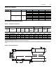
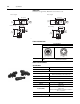
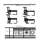
Bulletin 284, Continued Figure A.10 External Connections for Input Connector
Figure A.11 External Connections for Output Connector
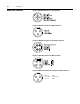
Figure A.12 External Connections for DeviceNet™ Connector
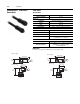
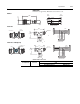
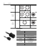
Figure A.13 External Connections for Motor Connector
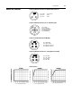
Figure A.14 External Connections for Control/Source Brake Connector
Pin 1: L1 - Black
Pin 2: GND - Green/Yellow
Pin 3: L2 - White