
Safety Version - User Manual User guide


Specifications A-7
Bulletin 284, Continued
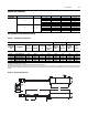
IP67 Dynamic Brake Resistor Ratings
Table A.1 IP67 Dynamic Brake Resistor
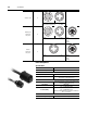
* - Indicates cable length (0.5 m or 1.0 m).
Note: Always check the resistor ohms against minimum resistance for drive being used.
Note: Duty Cycle listed is based on full speed to zero speed deceleration. For constance regen at full speed, duty cycle capability is half of what is listed. Application Type 1
represents maximum capability up to 100% braking torque where possible. Application Type 2 represents more than 100% braking torque where possible, up to a maximum
of 150%.
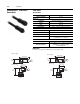
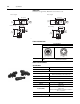
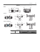
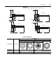
Figure A.9 Dynamic Brake Resistor
Line Voltage
Frequency 3-Phase kW Rating 3-Phase Hp Rating Output Current (A) Input Current (A)
Drive Ratings
380 50
0.4 — 1.4 2.15
0.75 — 2.3 3.80
1.5 — 4.0 6.40
2.2 — 6.0 9.00
3.0 — 7.6 12.40
460 60
— 0.5 1.4 1.85
—12.33.45
—24.05.57
—36.08.20
— 5 7.6 12.5
Application Type 1 Application Type 2
Drive and
Motor Size
kW
Part Number
Resistance
Ohms ± 5%
Continuous
Power kW
Max Energy
kJ
Max
Braking
Torque % of
Motor
Braking
Torque % of
Motor
Duty
Cycle %
Braking
Torque % of
Motor
Duty
Cycle %
400-480 Volt AC Input Drives
0.37 (0.5) 284R-360P500-M* 360 0.086 17 305% 100% 47% 150% 31%
0.75 (1) 284R-360P500-M* 360 0.086 17 220% 100% 23% 150% 15%
1.5 (2) 284R-360P500-M* 360 0.086 17 110% 100% 12% 110% 11%
2.2 (3) 284R-120P1K2-M* 120 0.26 52 197% 100% 24% 150% 16%
4 (5) 284R-120P1K2-M* 120 0.26 52 124% 100% 13% 124% 10%
H
J
F
C
G
B
D
E
A