
Safety Version - User Manual User guide


7-2 Explicit Messaging on DeviceNet™
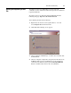
If a different I/O assembly is selected, the data size may change. It is
important to understand that the I/O assembly selected here will
directly affect the input and output mapping in the scanner’s scanlist
and the amount of Programmable Logic Controller (PLC) memory
reserved for this information.
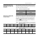
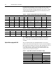
Table 7.2 Example SLC Input Addressing (Produced Assembly)
)
Table 7.3 Example SLC Output Addressing (Consumed Assembly)
)
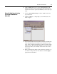
The example PLC program for the SLC will use the “Tripped” and
the “140M On” bit from the produced assembly and the “Fault
Reset”, “User Out A”, and “Run Fwd” bit from the consumed
assembly.
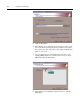
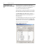
Explicit Messaging with SLC The 1747-SDN module uses the M0 and M1 file areas for data
transfer. Only words 224 through 256 are used to execute the Explicit
Message Request and Response function. The minimum data size for
the explicit message request is 6 words and the maximum is 32
words. The following tables illustrate the standard format of the
explicit message request and response.
Table 7.4 Explicit Message Request (Get_Attribute_Single)
)
Instance 161 Default Produced Standard Distributed Motor Controller
Byte 0 Bit 7 Bit 6 Bit 5 Bit 4 Bit 3 Bit 2 Bit 1 Bit 0
Address
I:1.23 I:1.22 I:1.21 I:1.20 I:1.19 I:1.18 I:1.17 I:1.16
Data
reserved Reserved reserved Ready Running Rev Running Fwd Warning Tripped
Byte 1
Bit 15 Bit 14 Bit 13 Bit 12 Bit 11 Bit 10 Bit 9 Bit 8
Address
I:1.31 I:1.30 I:1.29 I:1.28 I:1.27 I:1.26 I:1.25 I:1.24
Data
reserved Reserved 140M On HOA User In 3 User In 2 User In 1 User In 0
Instance 160 Default Consumed Standard Distributed Motor Controller
Byte Bit 7 Bit 6 Bit 5 Bit 4 Bit 3 Bit 2 Bit 1 Bit 0
Address
O:1.23 O:1.22 O:1.21 O:1.20 O:1.19 O:1.18 O:1.17 O:1.16
Data
User Out B User Out A reserved reserved reserved Fault Reset Run Rev Run Fwd
Bit location within Word
15 … 8 7 … 0
TXID COMMAND Word - 0
PORT SIZE Word - 1
SERVICE MAC ID Word - 2
CLASS Word - 3
INSTANCE Word - 4
ATTRIBUTE Word - 5