QUICK START ARMORSTART® DISTRIBUTED MOTOR CONTROLLER Getting Started BULLETIN 284D Introduction This guide provides the basic information required to start up your ArmorStart® Distributed Motor Controller. Factory default settings and information regarding installing, programming, and DeviceNet™ Node Commissioning are described here. For detailed information on specific product features or configurations, refer to the ArmorStart user manual, Publication 284-UM001*-EN-P.
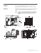
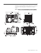
Installation The ArmorStart Distributed Motor Controller is convection cooled. Operating temperature must be kept between -20…40°C (-4…104°F). Dimensions Dimensions are shown in millimeters (inches). Dimensions are not intended to be used for manufacturing purposes. All dimensions are subject to change.
Dimensions are shown in millimeters (inches). Dimensions are not intended to be used for manufacturing purposes. All dimensions are subject to change.
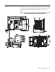
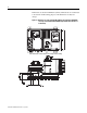
Dimensions are shown in millimeters (inches). Dimensions are not intended to be used for manufacturing purposes. All dimensions are subject to change.
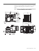
Dimensions are shown in millimeters (inches). Dimensions are not intended to be used for manufacturing purposes. All dimensions are subject to change.
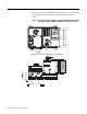
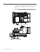
Dimensions are shown in millimeters (inches). Dimensions are not intended to be used for manufacturing purposes. All dimensions are subject to change.
Dimensions are shown in millimeters (inches). Dimensions are not intended to be used for manufacturing purposes. All dimensions are subject to change.
Dimensions are shown in millimeters (inches). Dimensions are not intended to be used for manufacturing purposes. All dimensions are subject to change.
Dimensions are shown in millimeters (inches). Dimensions are not intended to be used for manufacturing purposes. All dimensions are subject to change.
Wiring Power, Control, Safety Monitor Inputs, and Ground Wiring Table 1 provides the power, control, safety monitor inputs, ground wire capacity and the tightening torque requirements. The power, control, ground, and safety monitor terminals will accept a maximum of two wires per terminal.
Table 2 Power, Control, Safety Monitor, and Ground Terminal Designations Terminal Designations No. of Poles Description SM1 ➊ SM2 ➊ A1 (+) A2 (-) PE 1/L1 3/L3 5/L5 2 2 2 2 2 2 2 2 Safety Monitor Input Safety Monitor Input Control Power Input Control Power Common Ground Line Power Phase A Line Power Phase B Line Power Phase C ➊ Only available with the Safety Monitor option. Operation of NEMA Type 4X Disconnect Handle To Open Disconnect Handle 1. Rotate locking ring 45° until it stops. 2.
ArmorConnect Power Media Description The ArmorStart Power Media offers both three-phase and control power cable system of cordsets, patchcords, receptacles, tees, reducers and accessories to be utilized with the ArmorStart Distributed Motor Controller. These cable system components allow quick connection of ArmorStart Distributed Motor Controllers and reduce installation time.
Figure 11 Control Power Media System Overview Enclosure PLC Bulletin 1492FB Branch Circuit Protective Device Bulletin 1606 Power Supply 1606-XLSDNET4 DeviceNet Power Supply Bulletin 284 ArmorStart Bulletin 283 ArmorStart Bulletin 280/281 ArmorStart RESET OFF Bulletin 800F Emergency Stop Pushbutton ➏ Control Power Media Patchcords - PatchCord cable with integral female or male connector on each end Example Part Number: 889N-F65GFNM-* ➐ Control Power Tees - The E-stop In Tee (Part Number: 898N-653
ArmorStart with ArmorConnect Connectivity ArmorStart devices with 25 A short circuit protection rating ArmorStart devices with 10 A short circuit protection rating Control Power Receptacle Three-Phase Power Receptacle Control Power Receptacle Three-Phase Power Receptacle Installing ArmorConnect Power Media using Cord Grids Cord Grips for ArmorStart Devices with 10 A short circuit protection rating 3/4 in. Lock Nut Thomas & Betts Cord Grip Part Number: 2931NM 3/4 in.
Terminal Designations Description Color Code A1 (+) Control Power Input Blue A2 (-) Control Power Common Black PE Ground Green/Yellow 1/L1 Line Power - Phase A Black 2/L2 Line Power - Phase B White 3/L3 Line Power - Phase C Red ArmorConnect Cable Ratings The ArmorConnect Power Media cables are rated per UL Type TC 600V 90 °C Dry 75 °C Wet, Exposed Run (ER) or MTW 600V 90 °C or STOOW 105 °C 600V - CSA STOOW 600V FT2.
Group Motor Installations for USA and Canada Markets The ArmorStart Distributed Motor controllers are listed for use with each other in group installations per NFPA 79, Electrical Standard for Industrial Machinery. When applied according to the group motor installation requirements, two or more motors, of any rating or controller type, are permitted on a single branch circuit. Group Motor Installation has been successfully used for many years in the USA and Canada.
The working space around the ArmorStart may be minimized as the ArmorStart does not require examination, adjustment, servicing or maintenance while energized. In lieu of this service, the ArmorStart is meant to be unplugged and replaced after proper lockout/tag-out procedures have been employed.
AC Supply Considerations Ungrounded Distribution Systems ATTENTION ! The Bulletin 284 contains protective MOVs that are referenced to ground. These devices should be disconnected if the Bulletin 284 is installed on an ungrounded distribution system.
Figure 13 Jumper Removal Remove Jumper ATTENTION Do not remove this jumper if the unit is equipped with an EMI filter installed. ! LED Status Indication The LED Status Indication provides 4 status LEDs and a Reset button.
Figure 14 LED Status Indication and Reset DeviceNet Node Commissioning ATTENTION ! Three-phase power must be applied to the Bulletin 284 Distributed Motor Controller to gain access to drive parameters. Establishing a DeviceNet Node Address The ArmorStart is shipped with a default node address of 63 and Autobaud enabled. Each device on a DeviceNet network must have a unique node address or MAC ID which can be set to a value from 0…63.
To set an address using the hardware rotary switches, simply set the switches to the desired node address. To access the node address rotary switches, three-phase and control power should be turned off. Then remove the starter module from the base unit. The rotary node address switches are located on the back side of the starter module. Change the switches to the desired node address. Re-install the starter module to the base unit. Reapply power and the device will re-start at the new address.
Default Input and Output (I/O) Assembly Formats The I/O assembly formats for the ArmorStart are identified by the value in Parameter 11 (Consumed IO Assy.) and Parameter 12 (Produced IO Assy.). These values determine the amount and arrangement of the information communicated to the master scanner. The tables below identify the default information produced and consumed by Bulletin 284 devices.
Setting the Motor OL Current The product should now be configured and communicating on the network. The last step is to program the proper motor OL current setting (Parameter 133). This can be accomplished by using software such as RSNetWorx for DeviceNet or a handheld DeviceNet tool. Use the software to access the device parameters screen. By default the motor OL current is set to the minimum motor OL current setting for the device. Set this parameter to the desired value and download to the device.
Bulletin 284 Pararmeters Table 6 Basic Program Group for Sensorless Vector Performance Parameter Number Parameter Description Display/ Options Min./ Max. Defaults Settings 131 ➊ Motor NP Volts 1 VAC 20/Drive Rated Volts Based on Driving Rating 132 ➊ Motor NP Hz 1 Hz 10/240 Hz 60 Hz 133 Motor OL Current 0.1 A 0.0/(Drive Rated Amps x 2) Based on Driving Rating 134 Minimum Freq. 0.1 Hz 0.0/240 Hz 0.0 Hz 135 ➊ Maximum Freq. 0.1 Hz 0.
Table 7 Basic Program Group for Sensorless Vector Control Parameter Number Parameter Description Display/ Options Min./ Max. Defaults Settings 131 ➊ Motor NP Volts 1 VAC 20/Drive Rated Volts Based on Driving Rating 132 ➊ Motor NP Hz 1 Hz 15/400 Hz 60 Hz 133 Motor OL Current 0.1 A 0.0/(Drive Rated Amps x 2) Based on Driving Rating 134 Minimum Freq. 0.1 Hz 0.0/400 Hz 0.0 Hz 135 ➊ Maximum Freq. 0.1 Hz 0.
Quick Reference Troubleshooting There are four LEDs on the front of the ArmorStart that can provide an indication as to the health of the device. The following is a brief explanation of the operation of each LED. Table 8 LED Status Indication LED Definition Power This LED will be illuminated solid green when control power is present and with the proper polarity. This LED will be illuminated solid green when a start command and control power are present.
Fault LED Indications for Bulletin 284D ArmorStart Distributed Motor Controllers Table 10 Controller Fault LED Definitions Fault Definitions Blink Pattern ArmorStart Drive Controlled 1 Short (140M) — 2 — Overload Fault (Drive Error Codes 7 and 64) 3 — Phase Short (Drive Error Codes 41…43) 4 — Ground Fault (Drive Error Codes 13, 38…40) 5 — Motor Stalled (Drive Error Code 6) Possible Causes or Remedies 6 Control Power — 7 I/O Fault — 8 — 9 — Heatsink Overtemperature (Drive
Internal Drive Faults A fault is a condition that stops the drive. There are two fault types. Table 11 Internal Drive Fault Types Type Description 1 Auto-Reset/Run When this type of fault occurs, and Parameter 192 (Auto Rstrt Tries) Related Parameter(s): 155, 158, 161, 193 is set to a value greater than 0, a user-configurable timer, Parameter 193 (AutoRstrt Delay) Related Parameter(s): 192, begins. When the timer reaches zero, the drive attempts to automatically reset the fault.
Table 12 Fault Types, Descriptions, and Actions No. Fault Type ➊ Description Action F2 Auxiliary Input 1 Auxiliary input interlock is open. 1. 2. Check remote wiring. Verify communications. F3 Power Loss 2 DC bus voltage remained below 85% of nominal. 1. 2. Monitor the incoming AC line for low voltage or line power interruption. Check input fuses. F4 UnderVoltage 1 DC bus voltage fell below the minimum value. Monitor the incoming AC line for low voltage or line power interruption.
Table 12 Fault Types, Descriptions, and Actions (Continued) No. Fault Type ➊ Description Action F48 Params Defaulted 2 The drive was commanded to write default values to EEPROM. 1. 2. Clear the fault or cycle power to the drive. Program the drive parameters as needed. F63 SW OverCurrent 2 Programmed Parameter 198 [SW Current Trip] has been exceeded. Check load requirements and Parameter 198 (SW Current Trip) setting. F64 Drive Overload 2 Drive rating of 150% for 1 min.
Figure 17 Bulletin 284 ArmorStart Local Disconnect LED Status Indication 2 Outputs (Micro/M12) 4 Inputs (Micro/M12) Source Brake Connector Motor Ground Terminal DeviceNet Connection (Mini/M18) Connector Dynamic Brake Connector 0…10V➋ Analog Input ➋ Available only with the Bulletin 284 with sensorless vector control.
Accessories Table 13 DeviceNet Media ➊ 0 Description Length m (ft) Cat. No. Sealed KwikLink pigtail drops are Insulation Displacement Connector (IDC) with integral Class 1 round cables for interfacing devices or power supplies to flat cable Thick Cable 1485P-P1E4-B1-N5 1485P-P1E4-B2-N5 3 m (9.8) 1485P-P1E4-B3-N5 6 m (19.8) 1485P-P1E4-B6-N5 Right Keyway Left Keyway 1485P-P1N5-MN5NF 1485P-P1N5-MN5KM Connector Cat. No.
Table 14 Sensor Media ➊ 0 Description ArmorStart I/O Connection Pin Count Connector Cat. No.
Registered Trademark List ArmorPoint and ArmorStart are registered trademarks of Rockwell Automation, Inc. Trademark List ArmorConnect, RSLogix5000, PLC, RSNetWorx, and SLC are trademarks of Rockwell Automation, Inc. ControlNet is a trademark of ControlNet International, LTD. DeviceNet and the DeviceNet logo are trademarks of the Open Device Vendors Association (ODVA).