QUICK START ARMORSTART® DISTRIBUTED MOTOR CONTROLLER WITH ARMORPOINT® BACKPLANE Getting Started BULLETIN 284A Introduction This guide provides the basic information required to start up your ArmorStart® Distributed Motor Controller. Factory default settings and information regarding installing, programming, and ArmorPoint® Communication Protocol, are described here. For detailed information on specific product features or configurations, refer to the ArmorStart user manual, Publication 284-UM001*-EN-P.
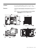
Installation The ArmorStart Distributed Motor Controller is convection cooled. Operating temperature must be kept between –20…40°C (–4…104°F). Dimensions Dimensions are shown in millimeters (inches). Dimensions are not intended to be used for manufacturing purposes. All dimensions are subject to change.
Dimensions are shown in millimeters (inches). Dimensions are not intended to be used for manufacturing purposes. All dimensions are subject to change.
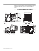
Dimensions are shown in millimeters (inches). Dimensions are not intended to be used for manufacturing purposes. All dimensions are subject to change.
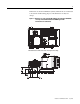
Dimensions are shown in millimeters (inches). Dimensions are not intended to be used for manufacturing purposes. All dimensions are subject to change.
Wiring Power, Control, Safety Monitor Inputs, and Ground Wiring Table 1 provides the power, control, safety monitor inputs, ground wire capacity and the tightening torque requirements. The power, control, ground, and safety monitor terminals will accept a maximum of two wires per terminal. Table 1 Terminal Designations Power, Control, Safety Monitor Inputs, Ground Wire Size, and Torque Specifications Terminals Wire Size Torque Wire Strip Length Power and Ground Primary/Secondary Terminal: 1.0…4.
Table 2 Power, Control, and Ground Terminal Designations Terminal Designations No. of Poles Description SM1 ➊ SM2 ➊ A1 (+) A2 (-) PE 1/L1 3/L3 5/L5 2 2 2 2 2 2 2 2 Safety Monitor Input Safety Monitor Input Control Power Input Control Power Common Ground Line Power Phase A Line Power Phase B Line Power Phase C ➊ Only available with the Safety Monitor option.
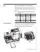
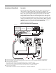
ArmorConnect Power Media Description The ArmorStart Power Media offers both three-phase and control power cable system of cordsets, patchcords, receptacles, tees, reducers and accessories to be utilized with the ArmorStart Distributed Motor Controller. These cable system components allow quick connection of ArmorStart Distributed Motor Controllers and reduce installation time.
Figure 7 Control Power Media System Overview Enclosure PLC Bulletin 1492FB Branch Circuit Protective Device Computer Terminal Bulletin 1606 Bulletin 1606 8 Ethernet Bulletin 280/281 ArmorStart Bulletin 284 ArmorStart ArmorPoint RESET 6 6 Bulletin 800F Emergency Stop Pushbutton 6 6 7 7 ➏ Control Power Media Patchcords - PatchCord cable with integral female or male connector on each end Example Part Number: 889N-F65GFNM-* ➐ Control Power Tees - The E-stop In Tee (Part Number: 898N-653ES-NKF
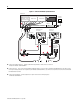
ArmorStart with ArmorConnect Connectivity ArmorStart devices with 25 A short circuit protection rating ArmorStart devices with 10 A short circuit protection rating Control Power Receptacle Three-Phase Power Receptacle Control Power Receptacle Three-Phase Power Receptacle Installing ArmorConnect Power Media using Cord Grips Cord Grips for ArmorStart Devices with 10 A short circuit protection rating 3/4 in. Lock Nut Thomas & Betts Cord Grip Part Number: 2931NM 3/4 in.
Terminal Designations Description Color Code A1 (+) Control Power Input Blue A2 (-) Control Power Common Black PE Ground Green/Yellow 1/L1 Line Power - Phase A Black 2/L2 Line Power - Phase B White 3/L3 Line Power - Phase C Red ArmorConnect Cable Ratings The ArmorConnect Power Media cables are rated per UL Type TC 600V 90 °C Dry 75 °C Wet, Exposed Run (ER) or MTW 600V 90 °C or STOOW 105 °C 600V - CSA STOOW 600V FT2.
Group Motor Installations for USA and Canada Markets The ArmorStart Distributed Motor controllers are listed for use with each other in group installations per NFPA 79, Electrical Standard for Industrial Machinery. When applied according to the group motor installation requirements, two or more motors, of any rating or controller type, are permitted on a single branch circuit. Group Motor Installation has been successfully used for many years in the USA and Canada.
meant to be unplugged and replaced after proper lockout/tag-out procedures have been employed. Since the ArmorStart is available with a factory installed HOA keypad option this may require the ArmorStart to be selected and installed as follows if the application requires frequent use of the hand operated interface by the equipment operator: 1. They are not less than 0.6 m (2 ft) above the servicing level and are within easy reach of the normal working position of the operator. 2.
Figure 8 Removal of Control Module Figure 9 Jumper Removal Remove Jumper ATTENTION Do not remove this jumper if the unit is equipped with an EMI filter installed.
LED Status Indication The LED Status Indication provides 4 status LEDs and a Reset button.
When connecting to the Bulletin 1738 ArmorPoint Distributed I/O product, a network adapter and at least one ArmorPoint Digital Output, Digital Input, Analog, AC and Relay product, or Specialty product must be selected. The ArmorPoint Distributed I/O product can accommodate up to 63 modules per network node. The cable that connects the ArmorPoint Distributed I/O to the ArmorStart Distributed Motor Controller is the Bulletin 280A-EXT1.
Details on Using the “ArmorStart Ladder Logic Configurator” The ArmorStart Ladder Logic Configurator is a ladder logic routine (File Name: ArmorStart_Configurator.ACD) designed so that under program control, the entire product family of the ArmorStart Distributed Motor Controllers can be configured easily from a Logix based controller. The family of ArmorStart Distributed Motor Controllers includes the following Bulletin Numbers: 280A, 281A, 283A and 284A.
Theory of Operation It is possible to connect an ArmorStart product to the Point I/O based subnet of the ArmorPoint I/O system. This allows the ArmorStart to be connected to EtherNetIP and ControlNet, along with the original DeviceNet. The easiest way to program these ArmorStarts is to use RSNetWorx for DeviceNet software, bridging through the appropriate network. This ladder logic has been developed as an alternate method of configuration.
I/O Tree Overview In order to transfer I/O information, the ArmorStart needs to be added to the I/O tree of the Logix processor. The details of doing this are outside of the scope of these instructions, but screen captures of the completed configuration are included below for reference. The configuration below shows the EtherNetIP card in the Logix chassis slot 1. The 1738-AENT module is always located at slot zero in the subnet and the ArmorStart device is located in slot 2 on the subnet.
Logic Configuration Details Inside the Configurator file is a large User Defined structure called Armor_Start_System, which contains all of the data for both the configuration of the routine, and also storage space for all of the ArmorStart parameters. With 20 devices, the total memory needed to hold this structure in the Logix controller is 195K bytes. The diagram below shows the upper part of the structure and 3 important elements. Figure 15 Configurator File — Armor_Start_System Armor_Start_System.
Figure 17 Array Size Parameter Armor_Start_System.Num_Devices defaults to zero and is defined as the total number of ArmorStart products connected to the control system that need to be configured. It is important that this value be set before the configuration routine is executed. It is to the users best advantage to trim the structures down to the minimum values that match their system because this will save a considerable amount of Logix processor memory.
Figure 18 Communication Card Configuration Note: To easily edit an ASCII string, click on the string value field and a small icon with three dots appears. Figure 19 String Browser Box Click on the three dots icon and a String Browser box appears. Modify the text to what is desired and click on Apply, then click on OK. This works for ALL strings throughout the entire data array.
modified. The parameter numbers all start with 1 and are numbered sequentially to the last parameter number. The user manual is important because it will thoroughly describe each parameter, for example, whether or not a parameter is writable and what the parameter limits/interpretation are. Once the device and parameter number is obtained, the next step is to modify the configuration data for that parameter.
Triggering a System Wide Read Once the system configuration has been done, a System Wide Read must be initiated. The logic to trigger both a System Wide Read and Write is contained in a subroutine called Handle_All_Armor. The rungs are shown below for reference. Figure 22 Handle_All_Armor Rungs To trigger the system wide read, the contact Read_All_Condition_Here needs to be energized in the ladder logic.
Interpreting the Error Report If an error occurs during the operation of the ladder logic, either the Write_All_System_Error_Flag or Read_All_System_Error_Flag bits will energize depending on which function was being triggered. Information will be logged inside the data structure Error_Report, that will aid in troubleshooting the problem. The format of this structure is shown below. Figure 23 Error Report The first element of this structure is .
Bulletin 284 Pararmeters Table 4 Basic Program Group for Sensorless Vector Performance Parameter Number Parameter Description Display/ Options Min./ Max. Defaults Settings 131 ➊ Motor NP Volts 1 VAC 20/Drive Rated Volts Based on Driving Rating 132 ➊ Motor NP Hz 1 Hz 10/240 Hz 60 Hz 133 Motor OL Current 0.1 A 0.0/(Drive Rated Amps x 2) Based on Driving Rating 134 Minimum Freq. 0.1 Hz 0.0/240 Hz 0.0 Hz 135 ➊ Maximum Freq. 0.1 Hz 0.
Table 5 Basic Program Group for Sensorless Vector Control Parameter Number Parameter Description Display/ Options Min./ Max. Defaults Settings 131 ➊ Motor NP Volts 1 VAC 20/Drive Rated Volts Based on Driving Rating 132 ➊ Motor NP Hz 1 Hz 15/400 Hz 60 Hz 133 Motor OL Current 0.1 A 0.0/(Drive Rated Amps x 2) Based on Driving Rating 134 Minimum Freq. 0.1 Hz 0.0/400 Hz 0.0 Hz 135 ➊ Maximum Freq. 0.1 Hz 0.
Quick Reference Troubleshooting There are four LEDs on the front of the ArmorStart that can provide an indication as to the health of the device. The following is a brief explanation of the operation of each LED. Table 6 LED Status Indication LED Definition Power This LED will be illuminated solid green when control power is present and with the proper polarity. Run This LED will be illuminated solid green when a start command and control power are present.
Fault LED Indications for Bulletin 284A ArmorStart Distributed Motor Controllers Table 8 Fault Definitions Blink Pattern ArmorStart Drive Controlled 1 Short (140M) — 2 — Overload Fault (Drive Error Codes 7 and 64) 3 — Phase Short (Drive Error Codes 41…43) 4 — Ground Fault (Drive Error Codes 13, 38…40) 5 — Motor Stalled (Drive Error Code 6) 6 Control Power 7 8 I/O Fault — 9 — 10 11 12 Reserved Internal Comm — — — Heatsink Overtemperature (Drive Error Code 8) Over-Current (Dr
Internal Drive Faults A fault is a condition that stops the drive. There are two fault types. Table 9 Internal Drive Fault Types Type Description 1 Auto-Reset/Run When this type of fault occurs, and Parameter 192 (Auto Rstrt Tries) Related Parameter(s): 155, 158, 161, 193 is set to a value greater than 0, a user-configurable timer, Parameter 193 (AutoRstrt Delay) Related Parameter(s): 192, begins. When the timer reaches zero, the drive attempts to automatically reset the fault.
Table 10 Fault Types, Descriptions, and Actions No. Fault Type ➊ Description Action F2 Auxiliary Input 1 Auxiliary input interlock is open. 1. 2. Check remote wiring. Verify communications. F3 Power Loss 2 DC bus voltage remained below 85% of nominal. 1. 2. Monitor the incoming AC line for low voltage or line power interruption. Check input fuses. F4 UnderVoltage 1 DC bus voltage fell below the minimum value. Monitor the incoming AC line for low voltage or line power interruption.
Table 10 Fault Types, Descriptions, and Actions (Continued) No. Fault Type ➊ Description Action F48 Params Defaulted 2 The drive was commanded to write default values to EEPROM. 1. 2. Clear the fault or cycle power to the drive. Program the drive parameters as needed. F63 SW OverCurrent 2 Programmed Parameter 198 [SW Current Trip] has been exceeded. Check load requirements and Parameter 198 (SW Current Trip) setting. F64 Drive Overload 2 Drive rating of 150% for 1 min.
Table 11 DeviceNet Media ➊ Accessories Description Length m (ft) Cat. No. Sealed KwikLink pigtail drops are Insulation Displacement Connector (IDC) with integral Class 1 round cables for interfacing devices or power supplies to flat cable 1 m (3.3) 1485P-P1E4-B1-N5 2 m (6.5) 1485P-P1E4-B2-N5 3 m (9.8) 1485P-P1E4-B3-N5 6 m (19.8) 1485P-P1E4-B6-N5 Right Keyway Left Keyway 1485P-P1N5-MN5NF 1485P-P1N5-MN5KM Connector Cat. No.
Table 13 Sensor Media ➊ Description ArmorStart I/O Connection Pin Count Connector Cat. No.
Bulletin 1738 ArmorPoint Distributed I/O Products Table 15 Digital I/O Products Description 0 Cat. No. 24V DC 8 Source Output w/ 8 M12 connectors 1738-OB8EM12 24V DC 8 Source Output w/ 8 M8 connectors 1738-OB8EM8 24V DC 4 Source Output w/ 4 M12 connectors 1738-OB4EM12 24V DC 4 Source Output w/ 4 M8 connectors 1738-OB4EM8 24V DC 2 Source Output w/ 2 M12 connectors 1738-OB2EM12 24V DC 2 Source Output - 2 A Prot.
Table 18 Power Supply Products Description 0 Cat. No. POINT I/O Field Potential Distributor Module 1738-FPD 24V DC Expansion Power Supply 1738-EP24DC Table 19 AC and Relay Products Description 0 Cat. No. 24V DC Coil N.O. DPST Relay w/ 2 M12 connectors 1738-OW4M12 24V DC Coil N.O.
Table 21 Adapter Products Description 0 Publication 284A-QS001C-EN-P - July 2006 Cat. No.
Registered Trademark List ArmorPoint and ArmorStart are registered trademarks of Rockwell Automation, Inc. Trademark List ArmorConnect, RSLogix5000, PLC, RSNetWorx, and SLC are trademarks of Rockwell Automation, Inc. ControlNet is a trademark of ControlNet International, LTD. DeviceNet and the DeviceNet logo are trademarks of the Open Device Vendors Association (ODVA).