
User Manual

Installation and Wiring 2-23
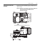
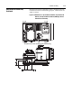
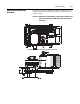
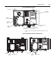
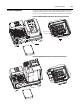
Figure 2.23 Bulletin 284 ArmorStart
①
Available only with the Bulletin 284 with sensorless vector con-
trol.
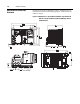
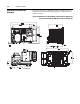
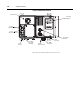
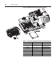
Figure 2.24 Bulletin 284 ArmorStart with ArmorConnect
LED Status
Indication
Motor
Connector
ArmorPoint
Interface
(Out)
Local Disconnect
2 Outputs
(Micro/M12)
Dynamic
Brake Connector
Source/Control Brake
Connector
0…10V Analog
①
Input Connector
ArmorPoint
Interface
(In)
Control
Control Power
Three-Phase Power
Three-Phase Power
Ground
Ter mi nal
Ground
Power
Ter mi nal