
User Manual

Specifications A-13
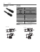
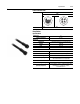
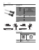
Bulletin 284, Continued Figure A.21 External Connections for Dynamic Brake Connector
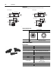
Figure A.22 External Connections for ArmorPoint® Interface (IN)
Figure A.23 External Connections for ArmorPoint Interface (OUT)
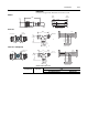
Figure A.24 External Connections for 0…10V Analog Input
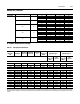
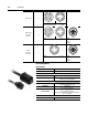
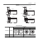
Overload Curves
Pin 1: GND - Green/Yellow
Pin 2: BR+ - Black
Pin 3: BR- - White
Pin 1: CAN High
Pin 2: Common
Pin 3: +5V
Pin 4: CAN Low
Pin 5: Enable In
Pin 7: Common
Pin 8: PE
Pin 1: CAN High
Pin 2: Common
Pin 3: +5V
Pin 4: CAN Low
Pin 5: Enable Out
Pin 7: Common
Pin 8: NC (No Connection)
Pin 1: 10V DC
Pin 2: 0…10V Input
Pin 3: Analog Common
Pin 4: Analog Output
Pin 5: RS485 Shield
% of P132 (Motor NP Hertz) % of P132 (Motor NP Hertz)
% of P132 (Motor NP Hertz)
% of P133 (Motor OL Current)
% of P133 (Motor OL Current)
% of P133 (Motor OL Current)