
User Manual

Product Overview 1-7
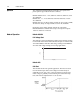
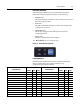
LED Status Indication
The LED Status Indication provides 4 status LEDs and a Reset
button. The LEDs provide status indication for the following:
•POWER LED
The LED is illuminated solid green when control power is present
and with the proper polarity
• RUN LED
This LED is illuminated solid green when a start command and
control power are present
•NETWORK LED
This bi-color (red/green) LED indicates the status of the
communication link
•FAULT LED
Indicates Controller Fault (Trip) condition
The “Reset Button” acts as a local trip reset.
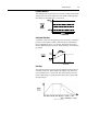
Figure 1.4 Status Indication and Reset
Fault Diagnostics
Fault diagnostics capabilities built in the ArmorStart Distributed
Motor Controller help you pinpoint a problem for easy
troubleshooting and quick re-starting.
➊ Not available on the Bulletin 280A/281A., 283A, or 284A.
Fault Indication
Available on Bulletin:
Fault Indication
Available on Bulletin:
280/281 283 284 280/281 283 284
• Short Circuit X X X • Miscellaneous Fault X X
• Overload X X X • Brake Fuse Detection X X
• Phase Loss X X X • Internal Comm. Fault X X
• Control Power Loss X X X • Shorted SCR X
• Control Power Fuse Detection X X X • Phase Rotation X
• Output Power Fuse Detection X X X • Heatsink Temperature Fault X
•I/O Fault X X X •DC Bus Fault X
• Over Temperature X X X • Ground Fault X
• DeviceNet™ Power Loss ➊ X X X • Overcurrent X
• EEprom Fault X X X • Restart Retries X
• Hardware Fault X X X • Stall X
• Phase Imbalance X X • Phase Short X