QUICK START ARMORSTART® DISTRIBUTED MOTOR CONTROLLER Getting Started BULLETIN 283D Introduction This guide provides the basic information required to start up your ArmorStart® Distributed Motor Controller. Factory default settings and information regarding installing, programming, and DeviceNet™ Node Commissioning are described here. For detailed information on specific product features or configurations, refer to the ArmorStart user manual, publication 283-UM001*-EN-P.
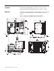
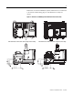
Installation The ArmorStart Distributed Motor Controller is convection cooled. Operating temperature must be kept between -20…40°C (-4…104°F). Dimensions Dimensions are shown in millimeters (inches). Dimensions are not intended to be used for manufacturing purposes. All dimensions are subject to change.
Dimensions are shown in millimeters (inches). Dimensions are not intended to be used for manufacturing purposes. All dimensions are subject to change.
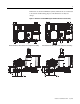
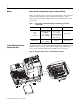
Dimensions are shown in millimeters (inches). Dimensions are not intended to be used for manufacturing purposes. All dimensions are subject to change.
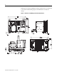
Dimensions are shown in millimeters (inches). Dimensions are not intended to be used for manufacturing purposes. All dimensions are subject to change.
Wiring Power, Control, Safety Monitor Inputs, and Ground Wiring Table 1 provides the power, control, safety monitor inputs, and ground wire capacity and the tightening torque requirements. The power, control, ground, and safety monitor terminals will accept a maximum of two wires per terminal.
Table 2 Power, Control, Safety Monitor, and Ground Terminal Designations Terminal Designations No. of Poles Description SM1 ➊ SM2 ➊ A1 (+) A2 (-) PE 1/L1 3/L3 5/L5 2 2 2 2 2 2 2 2 Safety Monitor Input Safety Monitor Input Control Power Input Control Power Common Ground Line Power Phase A Line Power Phase B Line Power Phase C ➊ Only available with the Safety Monitor option. Operation of NEMA Type 4X Disconnect Handle To Open Disconnect Handle 1. Rotate locking ring 45° until it stops. 2.
ArmorConnect Power Media Description The ArmorStart Power Media offers both three-phase and control power cable system of cordsets, patchcords, receptacles, tees, reducers and accessories to be utilized with the ArmorStart Distributed Motor Controller. These cable system components allow quick connection of ArmorStart Distributed Motor Controllers and reduce installation time.
Figure 7 Control Power Media System Overview Enclosure PLC Bulletin 1492FB Branch Circuit Protective Device Bulletin 1606 Power Supply 1606-XLSDNET4 DeviceNet Power Supply Bulletin 284 ArmorStart Bulletin 283 ArmorStart Bulletin 280/281 ArmorStart RESET OFF Bulletin 800F Emergency Stop Pushbutton ➏ Control Power Media Patchcords - PatchCord cable with integral female or male connector on each end Example Part Number: 889N-F65GFNM-* ➐ Control Power Tees - The E-stop In Tee (Part Number: 898N-653ES
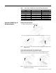
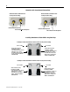
ArmorStart with ArmorConnect Connectivity ArmorStart devices with 25 A short circuit protection rating ArmorStart devices with 10 A short circuit protection rating Control Power Receptacle Three-Phase Power Receptacle Control Power Receptacle Three-Phase Power Receptacle Installing ArmorConnect Power Media using Cord Grips Cord Grips for ArmorStart Devices with 10 A short circuit protection rating 3/4 in. Lock Nut Thomas & Betts Cord Grip Part Number: 2931NM 3/4 in.
Terminal Designations Description Color Code A1 (+) Control Power Input Blue A2 (-) Control Power Common Black PE Ground Green/Yellow 1/L1 Line Power - Phase A Black 2/L2 Line Power - Phase B White 3/L3 Line Power - Phase C Red ArmorConnect Cable Ratings The ArmorConnect Power Media cables are rated per UL Type TC 600V 90 °C Dry 75 °C Wet, Exposed Run (ER) or MTW 600V 90 °C or STOOW 105 °C 600V - CSA STOOW 600V FT2.
Group Motor Installations for USA and Canada Markets The ArmorStart Distributed Motor controllers are listed for use with each other in group installations per NFPA 79, Electrical Standard for Industrial Machinery. When applied according to the group motor installation requirements, two or more motors, of any rating or controller type, are permitted on a single branch circuit. Group Motor Installation has been successfully used for many years in the USA and Canada.
maintenance while energized. In lieu of this service, the ArmorStart is meant to be unplugged and replaced after proper lockout/tag-out procedures have been employed. Since the ArmorStart is available with a factory installed HOA keypad option this may require the ArmorStart to be selected and installed as follows if the application requires frequent use of the hand operated interface by the equipment operator: 1. They are not less than 0.
LED Status Indication The LED Status Indication provides 4 status LEDs and a Reset button.
Node Commissioning using Hardware The ArmorStart is shipped with the hardware rotary switches set to a value of (99). If the switches are set to a value of (64) or above, the device will automatically configure itself to the software node address. If the switches are set to a value of (63) or less, the device will be at the node address designated by the switch configuration. To set an address using the hardware rotary switches, simply set the switches to the desired node address.
Table 3 Default I/O Messaging Data Default Message type Polled Consumed data size 1 byte (Rx) Produced data size 2 bytes (Tx) Default Input and Output (I/O) Assembly Formats The I/O assembly formats for the ArmorStart are identified by the value in parameter 11 (Consumed IO Assy.) and parameter 12 (Produced IO Assy.). These values determine the amount and arrangement of the information communicated to the master scanner.
Setting the Motor FLA Control power must be applied to the Bulletin 283 ATTENTION Distributed Motor Controller, to gain access to the soft starter parameters. ! The product should now be configured and communicating on the network. The last step is to program the proper motor FLA setting (parameter #106). This can be accomplished by using software such as RSNetWorx for DeviceNet or a handheld DeviceNet tool. Use the software to access the device parameters screen.
Quick Reference Troubleshooting There are four LEDs on the front of the ArmorStart that can provide an indication as to the health of the device. The following is a brief explanation of the operation of each LED. Table 6 LED Status Indication LED Power This LED will be illuminated solid green when control power is present and with the proper polarity. Run This LED will be illuminated solid green when a start command and control power are present.
Fault LED indications for Bulletin 283D ArmorStart Distributed Motor Controllers Table 8 Blink Pattern Definitions 3 The motor circuit protector has tripped, or the internal wiring protection algorithm has detected an unsafe current range. Try to reset the protector if tripped. If the condition continues, check the power wiring. This fault cannot be disabled. Overload trip The load has drawn excessive current and based on the trip class selected, the device has tripped.
Bulletin 283 Parameters Table 9 Starter Display and Parameter Settings Parameter Name String Path (hex) Min Max Dflt Type Value 101 102 103 104 105 Phase A Current Phase B Current Phase C Current Average Current % Therm Utilized 002C – 01 – 08 002C – 01 – 09 002C – 01 – 0A 002C – 01 – 05 002C – 01 – 07 32767 32767 32767 32767 100 — — — — — INT INT INT INT USINT xxx.x Amps xxx.x Amps xxx.x Amps xxx.
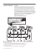
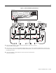
Figure 11 Bulletin 283 ArmorStart Local Disconnect LED Status Indication 2 Outputs (Micro/M12) Source Brake Connector 4 Inputs (Micro/M12) Motor Connection DeviceNet Connection (Mini/M18) Ground Terminal Figure 12 Bulletin 283 ArmorStart Ground Terminal Ground Terminal Control Power Three-Phase Power Control Power Three-Phase Power Publication 283D-QS001C-EN-P - July 2006
Table 11 DeviceNet Media ➊ Description Length m (ft) Cat. No. Sealed KwikLink pigtail drops are Insulation Displacement Connector (IDC) with integral Class 1 round cables for interfacing devices or power supplies to flat cable Thick Cable 1485P-P1E4-B1-N5 1485P-P1E4-B2-N5 3 m (9.8) 1485P-P1E4-B3-N5 6 m (19.8) 1485P-P1E4-B6-N5 Right Keyway Left Keyway 1485P-P1N5-MN5NF 1485P-P1N5-MN5KM Connector Cat. No.
Table 12 Sensor Media ➊ Description ArmorStart I/O Connection Pin Count Connector Cat. No.
Registered Trademark List ArmorPoint and ArmorStart are registered trademarks of Rockwell Automation, Inc. Trademark List ArmorConnect, RSLogix5000, PLC, RSNetWorx, and SLC are trademarks of Rockwell Automation, Inc. DeviceNet and the DeviceNet logo are trademarks of the Open Device Vendors Association (ODVA). Publication 283D-QS001C-EN-P — July 2006 Superecedes Publication 283D-QS001B-EN-P — September 2005 41053-384-05 (1) Copyright ©2006 Rockwell Automation, Inc. All Rights Reserved. Printed in USA.