QUICK START ARMORSTART® ETHERNET/IP DISTRIBUTED MOTOR CONTROLLER Getting Started BULLETIN 280E, 281E AND 284E Introduction This guide provides the basic information required to start up an ArmorStart® EtherNet/Industrial Protocol (IP) Distributed Motor Controller. For detailed information on specific product features or configurations, refer to the ArmorStart EtherNet/IP user manual, Publication 280E-UM001*.
ArmorStart EtherNet/IP Distributed Motor Controller Getting Started General Precautions In addition to the precautions listed throughout this manual, the following statements, which are general to the system, must be read and understood. ATTENTION: The controller contains ESD (electrostatic discharge) sensitive parts and assemblies. Static control precautions are required when installing, testing, servicing, or repairing the assembly.
ArmorStart EtherNet/IP Distributed Motor Controller Getting Started 3 ATTENTION: Only qualified personnel familiar with adjustable frequency AC drives and associated machinery should plan or implement the installation, startup, and subsequent maintenance of the system. Failure to do this may result in personal injury and/or equipment damage.
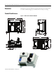
ArmorStart EtherNet/IP Distributed Motor Controller Getting Started Dimensions Dimensions are shown in millimeters (inches). Dimensions are not intended to be used for manufacturing purposes. All dimensions are subject to change. Conduit Gland Entrance Figure 3 – Dimensions for Bulletin 280E/281E 351 [13.82 ] 290 [11.42 ] 189 [7] 268 [10.55] 287,5 [11.32 ] 6,8 [.27 ] 150 [6 ] 3,02 [ .12 ] MOTOR CONNECTION 185 [7.3] M22 CORDSET MOTOR CONN ECTION 243 [9.57] M35 CORDSET 373 [14.69 ] 11 [ .
ArmorStart EtherNet/IP Distributed Motor Controller Getting Started 5 Conduit Gland Entrance Figure 4 – Dimensions for Bulletin 284E 2HP or less 420.38 [16.55] 3HP or greater 444.38 [17.50] 290 [11.42] 236 [9] 268 [10.55] 287,5 [11.32 ] 3,02 [.12 ] 6,8 [.27 ] MOTO R CONNECTION 266.9 [10.51] 373 [14.69] 11 [.43 ] 195 [7.68 ] 67,9 [3 ] 1" CONDUIT OPENING 39 [2 ] 47 [1.85 ] 0.
ArmorStart EtherNet/IP Distributed Motor Controller Getting Started ArmorConnect® Gland Connectivity Figure 5 – Dimensions for Bulletin 280E/281E 3 Hp and less @ 480V AC 10 Hp @ 480V AC 351 [13.82] 290 [11.42] 351 [13.82] 290 [11.42] 268 [10.55 ] 268 287,5 [10.55] [11.32 ] 203.2 [8] CABLE KEEP OUT 6,8 [.27 ] 10 Amp Short Circuit Protection (M22) 77,6 [3] 203.2 [8] CABLE KEEP OUT 6,8 [.27 ] 25 Amp Short Circuit Protection (M35) 77,6 [3 ] 60,6 [2 ] 25,5 [1 ] 60,6 [2 ] 68 [2.
ArmorStart EtherNet/IP Distributed Motor Controller Getting Started ArmorConnect Gland Connectivity Figure 6 – Dimensions for Bulletin 284E 2 Hp or less at 480V 290 [11.42] 3 Hp or greater at 480V 419,53 [16.52] 290 [11.42] 444,38 [17.50] 30,4 [1 ] 268 [10.55] 287,5 268 [10.55] [11.32] 6,8 [.27 ] 7 6,8 [.27 ] 10 Amp Short Circuit Protection (M22) 287,5 [11.32 ] 25 Amp Short Circuit Protection (M35) 77,6 [3 ] 77,6 [3] 60,6 [2 ] 60,6 [2] 25,5 [1] 68 [2.68 ] 25,5 [1 ] 68 [2.
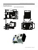
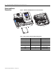
ArmorStart EtherNet/IP Distributed Motor Controller Getting Started Control and Power Connections Figure 7 – ArmorStart EtherNet/IP Power and Control Terminals Detail A See Detail A Table 1 - Power, Control and Ground Terminal Designations Publication 280E-QS001B-EN-P – February 2011 Terminal Designations No.
ArmorStart EtherNet/IP Distributed Motor Controller Getting Started 9 Recommended Cord Grips Figure 8 – Cord grips for ArmorStart Devices with 10 A Short Circuit Protection Rating 3/4 in. Lock Nut 1 in. Lock Nut Thomas & Betts Cord Grip Cat. No. 2931NM 3/4 in. Stain Relief Cord Connector Cable Range: 0.31…0.56 in. Used with Control Power Media Cordset - Example: Thomas & Betts Cord Grip Cat. No. 2940NM 1 in. Stain Relief Cord Connector Cable Range: 0.31…0.56 in.
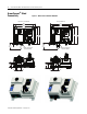
ArmorStart EtherNet/IP Distributed Motor Controller Getting Started Factory installed ArmorConnect gland plate connections Figure 11 – ArmorConnect Connections Table 2 - ArmorConnect Gland Plate Conductor Color Code Control Power Wiring Publication 280E-QS001B-EN-P – February 2011 Terminal Designations Description Color Code A1 (+) Control Power Input Blue A2 (–) Control Power Common Black A3 (+) Unswitched Control Power Red PE Ground Green/Yellow 1/L1 Line Power – Phase A Black 2
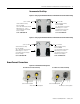
ArmorStart EtherNet/IP Distributed Motor Controller Getting Started 11 Figure 12 – Control Power Wiring Example 24V DC Control Power • Rated Operation Voltage – 24V DC (–15%, +10%) • A1 = Switched +V • A2 = Common for both switched and unswitched (–V) • A3 = Unswitched +V Group Motor Installations for USA and Canada Markets The ArmorStart Distributed Motor controllers are listed for use with each other in group installations per NFPA 79, Electrical Standard for Industrial Machinery.
ArmorStart EtherNet/IP Distributed Motor Controller Getting Started equipment or device as open wiring. The cable shall be secured at intervals not exceeding 1.8 m (6 ft) and installed in a “good workman-like” manner. Equipment grounding for the utilization equipment shall be provided by an equipment grounding conductor within the cable. *Historically cable meeting these crush and impact requirements were designated and marked “Open Wiring”.
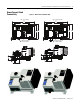
ArmorStart EtherNet/IP Distributed Motor Controller Getting Started ArmorStart Receptacle Pin Outs 13 Figure 13 – Receptacle Connections for EtherNet/IP (M12) Pin 1: Tx+ Pin 2: Rx+ Pin 3: Tx– Pin 4: Rx– Figure 14 – Receptacle Connections for Input (M12) Pin 1: +24V (A3 or DNET) Pin 2: Input 0 Pin 3: Common Pin 4: Input 1 Pin 5: NC (no connection) Figure 15 – Receptacle Connections for Output, EtherNet/IP Version (M12) Pin 1: NC (no connection) Pin 2: NC (no connection) Pin 3: Common Pin 4: Output +24V
ArmorStart EtherNet/IP Distributed Motor Controller Getting Started Figure 17 – Receptacle Connections for Incoming Control Power – 24V DC Only Pin 1: +24V DC unswitched (A3) (red) Pin 2: Common (A2) (black) Pin 3: PE (green) Pin 4: Not used (blank) Pin 5: +24V DC switched (A1) (blue) Pin 6: Not used (white) Figure 18 – Receptacle Connections for Source or Control Brake – Bulletin 284E only Pin 1: L1 (black) Pin 2: GND (green/yellow) Pin 3: L2 (white) Figure 19 – Receptacle Connections for Motor Conn
ArmorStart EtherNet/IP Distributed Motor Controller Getting Started 15 Figure 21 – Receptacle Connections for Incoming 3-Phase Power – 10 A Short Circuit Protection (M22) Pin 1: L1 (black) Pin 2: L2 (white) Pin 3: L3 (red) Pin 4: Ground (green/yellow) Figure 22 – Receptacle Connections for Incoming 3-Phase Power – 25 A Short Circuit Protection (M35) Pin 1: L1 (black) Pin 2: Ground (green/yellow) Pin 3: L3 (red) Pin 4: L2 (white) AC Supply Considerations for Bulletin 284E Units Ungrounded and High Resis
ArmorStart EtherNet/IP Distributed Motor Controller Getting Started Figure 23 – 284E Removal of Control Module Figure 24 – 284E Jumper Removal Remove Jumper ATTENTION: DO NOT remove this jumper if the unit is equipped with an EMI filter installed.
ArmorStart EtherNet/IP Distributed Motor Controller Getting Started Configuring EtherNet/IP Address 17 Before using the ArmorStart you may need to configure an IP address, subnet mask, and optional Gateway address. The rotary network address switches found on the I/O section of the ArmorStart are set to 999 and DHCP is enabled as the factory default. The ArmorStart reads these switches first to determine if the switches are set to a valid IP address between 1…254.
ArmorStart EtherNet/IP Distributed Motor Controller Getting Started Figure 26 – Network Address Example X10 X100 This example shows the IP address set to 163. 2 8 6 X1 0 0 4 0 2 8 6 4 2 8 6 4 The adapter’s subnet mask will be 255.255.255.0 and the gateway address is set to 0.0.0.0. A power cycle is required for any new IP address to take effect. If the switches are set to an invalid number (such as 000 or a value greater than 254), the adapter will check to see if DHCP is enabled.
ArmorStart EtherNet/IP Distributed Motor Controller Getting Started DHCP IP Support 19 DHCP (Dynamic Host Configuration Protocol) software automatically assigns IP addresses to client stations logging onto a TCP/IP network. When DHCP is enabled (factory default Enabled), the unit will request its network configuration from a DHCP/BOOTP server. Any configuration received from a DHCP server will be stored in non-volatile memory.
ArmorStart EtherNet/IP Distributed Motor Controller Getting Started Parameter Configuration ArmorStart Ethernet/IP embedded web server provides the user the ability to view and modify the device configuration without having to access RSLogix 5000. To view the device configuration from the web server, select the Parameters folder. For the parameter configuration, the user will login through the Administrative Settings or when prompted.
ArmorStart EtherNet/IP Distributed Motor Controller Getting Started ArmorStart EtherNet/IP Add-On Profile for Logix 21 The Add-On Profile (AOP) must be installed in order for RSLogix 5000 to fully support the ArmorStart EtherNet/IP product. The AOP can be downloaded from http://www.rockwellautomation.com/support/downloads.html. Example - Adding ArmorStart to RSLogix 5000 1. In the RSLogix 5000 tree select the Ethernet® adapter and add a new module.
ArmorStart EtherNet/IP Distributed Motor Controller Getting Started 2. Within the “Other” category select the ArmorStart. Figure 31 – Select Module Box 3. Configure the new module by adding a name and the IP address.
ArmorStart EtherNet/IP Distributed Motor Controller Getting Started 23 4. Go online with the controller via RSWho and download the project to the processor. Figure 33 – RSWho Box 5. Open the controller tags to view the units command, status, and diagnostic information.
ArmorStart EtherNet/IP Distributed Motor Controller Getting Started Diagnostics EtherNet/IP LED Status Indication Figure 35 – EtherNet/IP LED EtherNet/IP LED status and diagnostics consists of four LEDs.
ArmorStart EtherNet/IP Distributed Motor Controller Getting Started 25 Refer to Parameter 63 "Base Trip" for the Base Module Trip Status. Table 5 - "Steady Red" MOD LED Status (Refer to Table 4 above.) Fault Type Description 0 EEPROM Fault Non-volatile memory value out of range for a local parameter, or a write failure detected. This fault is also reflected by a solid red MOD status LED. 1 Internal Comm2 The Internal communication connection has timed out.
ArmorStart EtherNet/IP Distributed Motor Controller Getting Started Control Module Fault LED Indications Table 8 - Fault LED Indicators for Bulletin 280E/281E Blink Pattern AutoResettable Bulletin 280E/281E Trip Status 1 No Short Circuit The circuit breaker (140M) has tripped. Determine cause of trip. Try to reset the circuit breaker using the disconnect handle. If the conditions continue, check power wiring or replace based module. This cannot be disabled.
ArmorStart EtherNet/IP Distributed Motor Controller Getting Started 27 Table 9 - Fault LED Indicators for 284E Bit/Blink Pattern AutoResettable 1 No 2 284E Trip Status Description Action Short Circuit The circuit breaker (140M) has tripped. Determine cause of trip. Try to reset the circuit breaker using the disconnect handle. If the conditions continue, check power wiring or replace based module. This cannot be disabled.
ArmorStart EtherNet/IP Distributed Motor Controller Getting Started Table 9 - Fault LED Indicators for 284E Bit/Blink Pattern AutoResettable 13 No EEprom (PF Drive Code Reference 100) The checksum read from the board does not match the checksum calculated. Set Parameter 141 (Reset to Defaults) to Option 1 “Reset Defaults”. 14 No Hdw Flt (PF Drive Codes Reference 70 and 122) Failure has been detected in the drive power section or drive control and I/O section. 1. Cycle power. 2.
ArmorStart EtherNet/IP Distributed Motor Controller Getting Started 29 ATTENTION: Only qualified personnel familiar with adjustable frequency AC drives and associated machinery should plan or implement the installation, startup, and subsequent maintenance of the system. Failure to comply may result in personal injury and/or equipment damage. ATTENTION: This drive contains electrostatic discharge (ESD) – sensitive parts and assemblies.
ArmorStart EtherNet/IP Distributed Motor Controller Getting Started Bulletin 284E Troubleshooting Fault Definitions Some of the Bulletin 284E ArmorStart Distributed Motor Controller faults are detected by the internal hardware of the ArmorStart, while others are detected by the internal drive. For internal drive faults, the internal hardware of the ArmorStart simply polls the drive for the existence of faults and reports the fault state.
ArmorStart EtherNet/IP Distributed Motor Controller Getting Started 31 Internal Drive Faults A fault is a condition that stops the drive. There are two fault types. Type Description 1 Auto-Reset/Run When this type of fault occurs, Parameter 192 (Auto Rstrt Tries) and related Parameter(s): 155, 193 are set to a value greater than 0, a user-configurable timer, Parameter 193 (Auto Rstrt Delay) and related Parameter(s): 192, begins.
ArmorStart EtherNet/IP Distributed Motor Controller Getting Started The following table describes Bulletin 284E Faults as seen in Parameters 107, 108, and 109 (Fault 1, 2 or 3). No. Fault Type ➊ F2 Auxiliary Input 1 Auxiliary input interlock is open. 1. Check remote wiring. 2. Verify communications. F3 Power Loss 2 DC bus voltage remained below 85% of nominal. 3. Monitor the incoming AC line for low voltage or line power interruption. 4. Check input fuses.
ArmorStart EtherNet/IP Distributed Motor Controller Getting Started No. Fault Type ➊ F81 Comm Loss 2 RS485 (DSI) port stopped communicating. 27. Turn off using Parameter 205 (Comm Loss Action). 28. Replace starter module if fault cannot be cleared. F100 Parameter Checksum 2 The checksum read from the board does not match the checksum calculated. 29. Set Parameter 141 (Reset To Defaults) to Option 1 (Reset Defaults).
ArmorStart EtherNet/IP Distributed Motor Controller Getting Started Table 12 - Motor and/or Drive Will Not Accelerate to Commanded Speed Cause(s) Indication Corrective Action Speed command source or value is not as expected. None • Verify Parameter 102 (Commanded Freq). • Check Parameter 112 (Control Source) for the proper Speed Command. Programming is preventing the drive output from exceeding limiting values.
ArmorStart EtherNet/IP Distributed Motor Controller Getting Started 35 Control Module Removal ATTENTION: To avoid shock hazard, disconnect main power before working on the controller, motor, or control devices. 1. Disconnect power by going to the control module and turning OFF the At-Motor disconnect and performing lockout-tagout per your company policy. 2. Remove motor cable. 3. Loosen the four mounting screws. 4. Unplug the Control module from the base by pulling forward.
ArmorStart EtherNet/IP Distributed Motor Controller Getting Started Figure 40 – Control Voltage and Output Fuse Replacement Output Fuse Cat. No. W25176-155-03 Control Voltage Fuse Cat. No. W25172-260-17 Figure 41 – Source Brake Fuse Replacement (Bulletin 284E only) Source Control Brake Fuses Cat. No.
ArmorStart EtherNet/IP Distributed Motor Controller Getting Started 37 Basic Setup Parameters Bulletin 280E/281E/284E Programmable Parameters Additional configuration information and advanced settings help can be found in the ArmorStart User Manual, Publication 280E-UM001*. To configure the basic ArmorStart functionality refer to Table 16 below. These are the minimum setup configurations required for Bulletin 280E/281E or Bulletin 284E.
ArmorStart EtherNet/IP Distributed Motor Controller Getting Started Bulletin280E/281E Units Only Starter Display 101 Phase A Current 102 Phase B Current 103 Phase C Current 104 Average Current 105 Therm Utilized Starter Setup 106 FLA Setting 107 Overload Class 108 OL Reset Level Bulletin 284E Units Only Drive Display Drive Setup 101 Output Freq 102 Commanded Freq 103 Output Current 104 Output Voltage 105 DC Bus Voltage 106 Drive Status 107 Fault 1 Code 108 Fault 2 Code 109 Fault 3 Code 110 Process D
ArmorStart EtherNet/IP Distributed Motor Controller Getting Started 39 Default Input and Output (I/O) Assembly Formats The tables below identify the default information produced and consumed by Bulletin 280E, 281E and 284E. For additional formats and advance configurations please reference the user manual.
ArmorStart EtherNet/IP Distributed Motor Controller Getting Started Table 19 - Instance 151 Produce Assembly - Instance 151 “Drive Status” - 284E Starters Byte Bit 7 Bit 6 Bit 5 Bit 4 Bit 3 Bit 2 Bit 1 Bit 0 0 Reserve Reserve Reserve Reserve Reserve Reserve Reserve Reserve 1 Reserve Reserve Reserve Reserve Reserve Reserve Reserve Reserve 2 Reserve Reserve Reserve Reserve Reserve Reserve Reserve Reserve 3 Reserve Reserve Reserve Reserve Reserve Reserve Reserve
ArmorStart EtherNet/IP Distributed Motor Controller Getting Started 41 Notes: Publication 280E-QS001B-EN-P – February 2011
ArmorStart EtherNet/IP Distributed Motor Controller Getting Started Notes: Publication 280E-QS001B-EN-P – February 2011
ArmorStart EtherNet/IP Distributed Motor Controller Getting Started 43 Notes: Publication 280E-QS001B-EN-P – February 2011
Registered Trademark List ArmorConnect, ArmorStart, RSLinx and ControlLogix are registered trademarks of Rockwell Automation, Inc. Trademark List RSLogix 5000, is a trademarks of Rockwell Automation, Inc. EtherNet/IP, DeviceNet and the DeviceNet logo are trademarks of the Open Device Vendors Association (ODVA). Ethernet is a registered trademark of Digital Equipment Corporation, Intel, and Xerox Corporation.