
User Manual


Cable PinoutsB–4
Publication 2755-6.13
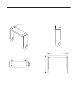
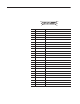
Power Supply Port
1
5
69
Pin Function
1 12V dc input power to the reader.
2 12V dc input power to the reader.
3 Earth ground
4 Power ground
5 Power ground
6 12V dc input power to the reader.
7 12V dc input power to the reader.
8 Power ground
9 Power ground
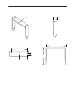
1
5
69
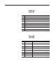
Pin Signal Function
1 Start of Scan Synchronizes decode logic with the scanner.
2 Digitized Bar Pattern
Input receives a series of pulses proportional to the
widths of bar code being scanned from the hand-held
scanner.
3 Decode LED Controls green decode LED on hand-held scanner.
5 Trigger Switch Connected to trigger switch of the hand-held scanner
6 Enable
Signal output to power up the hand-held scanner, turn
on the laser, and turn on the scanning motor.
7 Ground
8 Shield ground
9 Power +5V dc to power hand-held scanner
Note: Place a female contact in pin 4 of the 9–pin hand–held
connector.
Hand–Held Port Pinouts