
User Manual

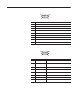

Cable Pinouts B–3
Publication 2755-6.13
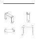
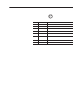
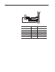
Interface Box Port
1
8
915
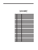
Pin Signal Function
1 RXD Reader receives data from the interface box.
2 CTS Reader is requesting data from the interface box.
3 Not Used Pin not used.
4 Not Used Pin not used.
5 Triac+ Controls the triac input.
6 Sensor+
Pin that provides the sensor ’s object detected input
signal.
7 Sensor Alarm+
Pin that provides the sensor ’s optional marginal sensing
alarm input signal.
8 Not Used Pin not used.
9 TXD Reader transmit data to the interface box.
10 RTS Interface box is requesting data from the reader.
11 GND Signal ground
12 Not used Pin not used.
13 Triac– Controls the triac input.
14 Sensor–
Pin that provides the sensor ’s object detected input
signal.
15 Sensor Alarm–
Pin that provides the sensor ’s optional marginal sensing
alarm input signal.