Allen-Bradley StrataScan Bar Code Readers (Cat. Nos.
Important User Information Because of the variety of uses for the products described in this publication, those responsible for the application and use of this control equipment must satisfy themselves that all necessary steps have been taken to assure that each application and use meets all performance and safety requirements, including any applicable laws, regulations, codes and standards.
toc–i Preface Chapter Objectives . . . . . . . . . . . . . . . . . . . . . . . . . . . . . . . . . . . Contents of this Manual . . . . . . . . . . . . . . . . . . . . . . . . . . . . . . . . Conventions Used in this Manual . . . . . . . . . . . . . . . . . . . . . . . . . Intended Audience . . . . . . . . . . . . . . . . . . . . . . . . . . . . . . . . . . . . Related Publication . . . . . . . . . . . . . . . . . . . . . . . . . . . . . . . . . . . Technical Support Services . . . . . . . . . . . . . . . .
toc–ii Master/slave Installation (Without Interface Box) . . . . . . . . . . . . . . . PLC or PC to the Reader, Reader to a Second Reader . . . . . . . . Master/slave Installation (With Interface Box) . . . . . . . . . . . . . . . . . PLC or PC to the Reader, Interface Box, and a Second Reader . . Maintenance and Troubleshooting Chapter 5 Specifications Appendix A Cleaning the Scan Window . . . . . . . . . . . . . . . . . . . . . . . . . . . . . . Troubleshooting the Readers . . . . . . . . . . . . .
Chapter Objectives Read this chapter to familiarize yourself with the rest of the manual. You will learn about: • contents of this manual • conventions used in this manual • intended audience • related publications • technical support Contents of this Manual The following table describes the contents of this manual. Chapter Title Contents Preface Describes the purpose, background, and scope of this manual. Also specifies the audience for whom this manual is intended.
P–2 Preface Conventions Used in this Manual The following conventions are used throughout this manual. • Bulleted lists such as this one provide information, not procedural steps. • Numbered lists provide sequential steps. • Italic type is used for emphasis. • Text within square brackets in this font represent the keys you press. Intended Audience No special knowledge is required to understand this document or use the StrataScan Bar Code Readers (Catalog Nos.
Introduction to StrataScan Bar Code Readers This chapter can help you to get started using the StrataScan Bar Code Readers. We base the procedures here on the assumption that you have an understanding of bar code readers and control equipment. Because it is an introduction, this chapter does not contain detailed explanations about the procedures listed. It does, however, reference other chapters in this book where you can get more information.
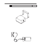
1–2 Introduction to StrataScan Bar Code Readers Procedures 1. Check the contents of shipping boxes. Unpack the shipping boxes while making sure that the contents include: • • • • • • • StrataScan Holographic reader (Catalog No. 2755–LHR–5B, –3C, –5C or 5BX1) Reference Chapter 4 (Installing Your Hardware) Mounting bracket (Catalog No. 77126–898–01 or –02) Power supply (12V dc) (Catalog No. 77126–896–01) Disk-based Hardware User Manual (Catalog No. 2755–6.
Introduction to StrataScan Bar Code Readers 3. Install the reader. 1–3 Reference Mount the reader(s) (Catalog Nos. 2755-LHR–3C, 2755-LHR–5C, 2755-LHR–5B, 2755-LHR–5BX1) to the mounting bracket(s) (Catalog No. 77126–898–01 or 77126–898–02). Chapter 4 (Installing Your Hardware) Mounting Bracket Reader Make sure placement of the mounting bracket allows you to connect the reader to the interface box (Catalog No. 2755-LHB–1). Skip this information and step #4 if you are not using an interface box.
1–4 Introduction to StrataScan Bar Code Readers 4. Install the interface box. Reference Mount the interface box to your mounting surface after having attached the sensor/relay leads to the sensor terminal block inside the interface box. Make sure that the 3 power leads from the interface box power cord are connected to their correct locations on the power terminal block and grounding posts terminals inside the interface box case.
Introduction to StrataScan Bar Code Readers 5. Install the power supply. Reference Place the power supply (Catalog No. 77126–896–01) within 12 ft. (3.66 m) of the scanner. 6. 1–5 Chapter 4 (Installing Your Hardware) Connect the hardware components together. Reference Chapter 4 (Installing Your Hardware) If you are using an interface box, connect the reader, power supply and package detect to the interface box.
1–6 Introduction to StrataScan Bar Code Readers 8. Check the reader defaults, program as needed. Make sure you have DOS or Windows–based software on your personal computer. Run StrataSet Programming software, Catalog No. 2755–LHS–1. Make sure that communications has been established with your reader. e.g., read a test bar code to verify that the default settings are correct (i.e., the reader is communicating with the configuration device). Program as needed. 9.
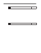
Hardware Features This chapter describes the features of the StrataScan Bar Code Readers (Catalog Nos. 2755-LHR-5B, 2755-LHR-3C, 2755-LHR-5C and 2755-LHR-5BX1) and interface box (Catalog No. 2755-LHB-1). Included are descriptions of: • reader features • interface box features • decoding • safety information • scan beam options • accessories Reader Features The reader features are shown below. Scan Window Mounting Bracket Speaker LEDs Ports Publication 2755-6.
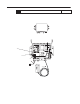
2–2 Hardware Features Holographic Scanning Disc The rotating holographic disc takes the place of a focusing lens, light collection lens, and a rotating mirror. The disc contains 15 to 21 separate holographic sectors. Each sector has its own focal distance, light collection aperture, and mirror scan angle. As the disc rotates, each sector is operational, providing the reader an excellent opportunity to scan a bar code symbol.
Hardware Features 2–3 Disc Operation As the disc rotates, the laser beam hits the disc. The laser beam is then projected onto the mirror and then projected out through the reader’s window. The reflected light travels toward the mirror. The reflected light is then projected onto the rotating disc where it is detected by an internal sensor. Bar Code Reflected Light Laser Beam Detector Mirror Scan Disc Laser Reader LEDs There is one green and one red LED on the readers.
2–4 Hardware Features Interface Box Features The interface box routes signals between the readers and an external package detect. The interface box has the following components: • Power transformer. Supplies a stepped down and isolated voltage that produces the 12V dc power for the interface box and external sensor. • F2 control fuse holder. Contains the 12V dc fuse for the interface box. • F1 triac fuse holder. Contains the fuse for the triac output. • Power terminal block.
Hardware Features Decoding 2–5 The readers can decode the following symbologies: • UPC/EAN • Codabar • Code 11 • Code 39 • Code 39 Full ASCII • Code 39 Mod 43 • Code 93 • Code 128 • Interleaved 2 of 5 • Interleaved 2 of 5 Mod 10 • Paraf • MSI Plessey • MSI Plessey Mod 10 Check digit • MSI Plessey Mod 10/10 Check digit • UK Plessey • Airline 2 of 5 • Matrix 2 of 5 • telepen Refer to Chapter 2 of StrataSet Programming Software Programming Guide (Publication No. 2755–6.
2–6 Hardware Features Safety Information This equipment has been tested and found to comply with limits for a Class A digital device, pursuant to Part 15 of the FCC Rules. These limits are designed to provide reasonable protection against harmful interference when the equipment is operated in a commercial environment.
Hardware Features 2–7 Laser Labels Be aware of the following laser caution, danger and avoid exposure labels on the readers. Their locations vary depending upon reader catalog number shown below: DANGER – Laser light when open. AVOID DIRECT EXPOSURE TO BEAM (hidden from view) AVOID EXPOSURE Laser light is emitted from this aperture. DANGER – Laser light when open. AVOID DIRECT EXPOSURE TO BEAM (hidden from view) AVOID EXPOSURE Laser light is emitted from this aperture.
2–8 Hardware Features Scan Beam Strata Scan beams are projected to focus in different strata as shown below. The various overlapping focus areas give the StrataScan holographic reader its great depth of field. Note: Publication 2755-6.13 This pattern or number of strata is different for each of the reader models.
Hardware Features Reader Catalog Numbers The following readers have their corresponding catalog numbers: Description Accessories 2–9 Catalog Number High density, five laser holographic reader 2755-LHR-5B Medium density, three laser holographic reader 2755-LHR-3C Medium density, five laser holographic reader 2755-LHR-5C High density, five laser holographic reader 2755-LHR-5BX1 The following accessories are available with the readers: Description Catalog Number Interface box 2755-LHB-1 Maste
Designing Your System This chapter provides the information needed to set up a scanner system correctly. Items include: • setup goals • symbol height and length • symbol quality • symbol orientation • tilt, pitch, and skew • determining read range Setup Goals Each application must be evaluated carefully. Successful bar code scanning begins with quality bar code symbols and the correct number, type, and location of readers, decoders, and package sensors.
3–2 Designing Your System Symbol Height and Length The height is measured from one end of a bar to the other, and its length is always the distance from one end of the symbol to the other, including the Quiet Zones. A Quiet Zone is the empty space before or after the bars, and is usually equal to 10 times the Narrow Element Width. H Symbol Length = L Symbol Height = H Quiet Zones L Quiet Zones The aspect ratio (symbol height to symbol length) cannot be greater than 1.7:1 for Catalog No.
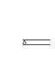
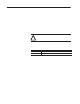
Designing Your System Symbol Orientation 3–3 Bar code symbols must have the correct aspect ratio to be read by the reader. A scan line must cross every bar, space, and both quiet zones on the same sweep. Correct: All bars are crossed by a scan line Not Correct: Some bars are not crossed by a scan line Tilt, Pitch, and Skew Refer to the figure below for various package orientations.
3–4 Designing Your System Tilt A symbol is tilted when the symbol’s bars are not 90° to one of the scan lines. The symbol can be read with any tilt, provided a scan line passes through all bars and quiet zones on each sweep for the required minimum number of scans. Tilt may reduce the number of scans in a given application. Pitch A symbol is pitched when the symbol’s bars are at different distances from the reader.
Designing Your System Determining Read Range 3–5 The readers can read bar code symbols at various distances depending upon the type of reader and the narrowest bar code element width (width of smallest bar or space). Minimum Bar Code Width Catalog Number 2755-LHR-5B 2755-LHR-3C 2755-LHR-5C 2755-LHR-5BX1 Maximum Scan Width Read Range 0.008 in. (0.20 mm) 18 to 38 in. (45.7 to 96.5 cm) 12 in. (30.5 cm) 0.025 in. (0.64 mm) 18 to 38 in. (45.7 to 96.5 cm) 12 in. (30.5 cm) 0.013 in. (0.
Installing Your Hardware This chapter provides the information needed to install the readers, their mounting brackets, their power supplies, and interface boxes. Items include: • RS-232 installations • master/slave installations Because of the variety of uses for the information, users of and those responsible for applying this information must satisfy themselves as to the acceptability of each application and use of the program.
4–2 Installing Your Hardware RS232 Installations Refer to the following sections to install your system hardware, based on the type of equipment you select: PLC or PC to the Reader 1. Make sure your system is planned properly. Refer to Chapter 3 for information about planning your system. 2. Refer to Appendix A for dimensions of readers, mounting brackets, power supplies, and interface boxes. Cable pinouts are shown in Appendix B. 3. Install the mounting bracket (Catalog Nos.
Installing Your Hardware 4–3 6. Connect the null modem cable (Catalog No. 2755-LHC-11) to the PLC or PC (9–pin connector) and the reader (25–pin connector). 7. Place the power supply (Catalog No. 77126-896-01) within 12 ft. (3.66 m) of the reader. Connect the power supply to the reader. Power Supply To Power Receptacle Grounding Pin 77126–896–01 To Reader (9-pin connector) 2755–LHC–11 To Reader (25-pin connector) To PC (9-pin connector) Reader 8.
4–4 Installing Your Hardware PLC or PC to the Reader and Interface Box 1. Make sure your system is planned properly. Refer to Chapter 3 for information about planning your system. 2. Refer to Appendix A for dimensions of readers, mounting brackets, power supplies, and interface boxes. Cable pinouts are shown in Appendix B. 3. Install the mounting bracket (Catalog Nos. 77126-898-01 or 77126-898-02) for the readers (Catalog Nos. 2755-LHR-5B, 2755-LHR-3C, 2755-LHR-5C, and 2755-LHR-5BX1).
Installing Your Hardware 4–5 6. Connect the null modem cable (Catalog No. 2755-LHC-11) to the PLC or PC (9–pin connector) and the reader (25–pin connector). 7. Place the power supply (Catalog No. 77126-896-01) within 12 ft. (3.66 m) of the reader. Connect the power supply to the reader. 8. Connect the interface box cable (Catalog No. 2755-LHC-2) to the interface box and the reader. The 15–pin end of the cable connects to the reader and the 8–pin end to the interface box.
4–6 Installing Your Hardware Sensor Terminal Block Interface Box Common Sensor Cable +12V out Sink in Sensor housing 10. Mount the interface box (Catalog No. 2755-LHB-1). Its dimensions are shown in Appendix A. Screw Holes Publication 2755-6.
Installing Your Hardware ! ATTENTION: Before connecting power, make sure that the 3 power leads from the interface box power cord are connected to their proper locations on the power terminal block and grounding posts inside the interface box case. A domestic and a European example are shown in the following illustration. Make sure that the interface box is connected to an ac source per local/regional electrical codes.
4–8 Installing Your Hardware Master/slave Installation (Without Interface Box) Refer to the following steps to install your system hardware: PLC or PC to the Reader, Reader to a Second Reader 1. Make sure your system is planned properly. Refer to Chapter 3 for information about planning your system. 2. Refer to Appendix A for dimensions of readers, mounting brackets, power supplies and interface boxes. Cable pinouts are shown in Appendix B. 3. Install the mounting brackets (Catalog Nos.
Installing Your Hardware 4–9 6. Connect the PLC or PC to the master reader (25–pin connector). 7. Connect the Master/Slave cable (Catalog No. 2755-LHC-1) to the first reader (master) and the second reader (slave). The 15-pin end of the cable connects to the master reader. 8. Connect the 25-pin end of the cable to the slave reader. 9. Connect each reader to a power supply.
4–10 Installing Your Hardware ! ATTENTION: To prevent unsuccessful programming of your master/slave scanner configuration, follow this setup sequence when installing master/slave option: 1. Connect master and slave scanners with the appropriate master/slave cable. 2. Connect Allen–Bradley StrataScan Configuration software to the master scanner. 3. Apply power to the master/slave units. 4. Program the master scanner as you would a regular scanner with the StrataScan Configuration software. 5.
Installing Your Hardware 4–11 4. Mount each reader to its mounting bracket. Mounting Bracket Reader 5. Install your PLC or PC. For proper installation refer to the installation information provided with each product. Publication 2755-6.
4–12 Installing Your Hardware 6. Connect the PLC or PC to the first reader. 7. Connect the Master/Slave Interface Box Cable (Catalog No. 2755-LHC-3) to the first reader (master) and the interface box. Make sure you lock into place the interface box end of the cable. The 15-pin end of the cable connects to the master reader. 8. Connect each reader to a power supply. 9. Connect the Master/Slave Interface Box Cable (Catalog No. 2755-LHC-3) to the second reader (slave).
Installing Your Hardware ! ATTENTION: Before connecting power, make sure that the 3 power leads from the interface box power cord are connected to their proper locations on the power terminal block and grounding posts inside the interface box case. A domestic and a European example are shown in the following illustration. Make sure that the interface box is connected to an ac source per local/regional electrical codes.
4–14 Installing Your Hardware When power is applied to each reader, the green LED flashes on and off, then the red LED turns on and remains on. A beep is emitted from each reader as well, indicating the reader has power. Scan beams are also emitted from each reader. When power is applied to the interface box, the green 12V LED turns on and remains on. Publication 2755-6.
Maintenance and Troubleshooting This chapter provides information on how to maintain and troubleshoot your StrataScan hardware. Items include: • cleaning the scan window • troubleshooting the readers • contacting Technical Support ! Cleaning the Scan Window CAUTION!: Before cleaning window, make sure that power to the reader is off. Failure to disconnect power may cause exposure to laser light.
5–2 Maintenance and Troubleshooting Troubleshooting the Readers The following table provides a list of the most common operating problems, probable causes, and corrective actions. Problem No blinking Green LED Possible Cause (s) No power Corrective Action No Motor Spin No power Blinking Green LED Motherboard problem No Motor Spin 1. Motherboard problem Contact an Allen–Bradley service representative. 2. Reader is in motor failure condition. 1. Motor may be defective.
Maintenance and Troubleshooting Problem Reader does not enter Program mode Possible Cause (s) 5–3 Corrective Action 1. Host COM Port not working properly 1. Check to see if cable connection to COM Port is correct. 2. Wrong COM Port 2. Make sure COM Port selection in StrataScan configuration software is correct. 3.
5–4 Maintenance and Troubleshooting Problem Possible Cause (s) 1. Print quality of the bar code is suspect. Cannot read bar code➂ 2. The aspect ratio of the bar code is out of tolerance. 3. The bar code may have been printed incorrectly. DOS error code: # 68 – Device unavailable DOS error code: # 24 – Device timeout ➂ Corrective Action To verify the basic operation of the reader, configure the reader with the standard default settings.
Maintenance and Troubleshooting Technical Support Services 5–5 If you have any questions about the StrataScan Bar Code Reader, please consult this manual first. If you can’t find the answer, contact your local Allen-Bradley support office or distributor. Publication 2755-6.
This appendix provides the specifications and dimensions for the: • StrataScan Bar Code Readers (Catalog Nos. 2755-LHR-5B, 2755-LHR-3C, 2755-LHR-5C and 2755–LHR–5BX1) • interface box (Catalog No. 2755-LHB-1) • replacement power supply (Replacement Part No. 77126-896-01) • replacement mounting brackets for readers (Replacement Part Nos. 77126-898-01 and 77126-898-02) Publication 2755-6.
A–2 Specifications StrataScan Bar Code Reader Specifications The following table provides the specifications for the StrataScan Bar Code Readers (Catalog Nos. 2755-LHR-5B, 2755-LHR-3C, and 2755-LHR-5C). Specification Description Catalog No. 2755-LHR-5B Catalog No. 2755-LHR-3C Catalog No.
Specifications A–3 Interface Box Specifications Description Catalog Number Specification 2755-LHB-1 Electrical Characteristics Input Voltage UL and cUL 100, 115, or 230V ac at 50 Hz, 60 Hz 6.1 A CE 115, 230V ac at 50 Hz, 60 Hz 5.1A Relay Triac, 5 A EEA Countries 6 A USA and Canada Output for Sensor +12V dc @ 200 mA Operating Temperature 32 F to 122 F (0 C to 50 C) Humidity 5% to 95% noncondensing Agency Certification • cUL listed • UL listed • CE marked for all applicable directives.
A–4 Specifications StrataScan Bar Code Reader Dimensions Reader dimensions are shown below: Catalog Number 2755-LHR-5B Front View Side View 5.75 in. (14.6 cm) 11.45 in. (29.1 cm) 11.12 in. (28.2 cm) Catalog Numbers 2755-LHR-3C, -5C and -5BX1 Front View Side View 7.25 in. (18.4 cm) 15.19 in. (38.6 cm) Publication 2755-6.13 14.31 in. (36.
Specifications Interface Box Dimensions A–5 Dimensions for the interface box are shown below: Catalog Number 2755-LHB-1 Front View Top View 3.25 in. (8.26 cm) 6.0 in. (15.24 cm) 5.31 in. (13.48 cm) 7.4 in. (18.89 cm) Power Supply Dimensions Power supply dimensions are shown below: Replacement Part Number 77126-896-01 Front View 1.50 in. (3.81 cm) 1.59 in. (4.04 cm) 5.73 in. (14.55 cm) Top View Side View 2.54 in. (6.45 cm) 5.77 in. (14.66 cm) 2.50 in. (6.35 cm) Publication 2755-6.
A–6 Specifications Mounting Bracket Dimensions Mounting bracket dimensions for all StrataScan readers are shown starting below: Replacement Part Number 77126-898-01 (for reader 2755-LHR-5B) 0.41 in. (1.04 cm) 3.25 in. (8.26 cm) Side View 11.00 in. (27.94 cm) 8.25 in. (20.96 cm) 1.50 in. (3.81 cm) Top View Publication 2755-6.13 9.75 in. (24.
Specifications A–7 Replacement Part Number 77126-898-02 (for readers 2755-LHR-3C, -5C and -5BX1) 3.25 in. 0.41 in. (1.04 cm) (8.26 cm) Side View 14.75 in. (37.47 cm) 12.00 in. (30.48 cm) 1.50 in. (3.81 cm) 11.19 in. (28.42 cm) 6.00 in. (15.24 cm) Top View Front View Publication 2755-6.
Cable Pinouts This appendix provides the cable pinouts for the readers, interface box, power supply, and assorted cables. Publication 2755-6.
B–2 Cable Pinouts Reader Pinouts The following sections provide the pinouts for the StrataScan Bar Code Readers (Catalog Nos. 2755-LHR-5B,-3C, -5C and 5BX1). RS-232 Port 1 13 14 Pin Publication 2755-6.13 25 Signal Function 1 GND Chassis ground 2 RXD Reader receives data from the host device. 3 TXD Reader transmits data to the host device. 4 CTS Input Reader is requesting data from the host device. 5 RTS Output Host device is requesting data from the reader.
Cable Pinouts B–3 Interface Box Port 1 8 9 Pin 15 Signal Function 1 RXD Reader receives data from the interface box. 2 CTS Reader is requesting data from the interface box. 3 Not Used Pin not used. 4 Not Used Pin not used. 5 Triac+ Controls the triac input. 6 Sensor+ Pin that provides the sensor’s object detected input signal. 7 Sensor Alarm+ Pin that provides the sensor’s optional marginal sensing alarm input signal. 8 Not Used Pin not used.
B–4 Cable Pinouts Power Supply Port 1 5 6 9 Pin Function 1 12V dc input power to the reader. 2 12V dc input power to the reader. 3 Earth ground 4 Power ground 5 Power ground 6 12V dc input power to the reader. 7 12V dc input power to the reader. 8 Power ground 9 Power ground Hand–Held Port Pinouts 1 5 6 Pin Signal 9 Function 1 Start of Scan Synchronizes decode logic with the scanner.
Cable Pinouts B–5 Interface Box Pinouts G H A B F E C D Pin Signal Function A Triac+ Controls the triac input. B Triac– Controls the triac input. C Sensor+ Provides the sensor’s object detected input signal. D Sensor– Provides the sensor’s object detected input signal. E Sensor Alarm Provides the sensor’s optional marginal sensing alarm input signal. F Sensor Alarm Provides the sensor’s optional marginal sensing alarm input signal. G Not Used Pin not used.
B–6 Cable Pinouts Power Supply Pinouts 1 5 6 9 Pin Publication 2755-6.13 Function 1 12V dc input power to the reader. 2 12V dc input power to the reader. 3 Earth ground 4 Power ground 5 Power ground 6 12V dc input power to the reader. 7 12V dc input power to the reader.
Cable Pinouts Reader Master/slave Cable Pinouts B–7 Slave Reader Connector Master Reader Connector 13 25 1 9 15 8 1 14 Master Reader Connector (15-Pin) Pin Number Signal from Master Reader Slave Reader Connector (25-Pin) Pin Number 1 RXD (input) 3 2 CTS (output) 4 9 TXD (output) 2 10 RTS (input) 5 11 GND 7 Publication 2755-6.
B–8 Cable Pinouts Reader Null Modem Cable Pinouts Reader Connector 13 PC or PLC Connector 25 1 6 9 5 1 Publication 2755-6.
Cable Pinouts Interface Box Cable Pinouts B–9 Reader Connector 9 1 Interface Box Connector A H G F B C E D 15 8 Reader Connector (15-Pin) Pin Number Signal from Reader Interface Box Connector (8-Pin) Pin Number 5 Triac+ A 13 Triac– B 6 Sensor+ C 14 Sensor– D 7 Sensor alarm+ E 15 Sensor alarm– F Publication 2755-6.
B–10 Cable Pinouts Interface Box Master/slave Cable Pinouts Slave Reader Connector Master Reader Connector 9 Interface Box Connector H A 13 25 1 G F B C E D 15 8 14 1 Publication 2755-6.
European Union Directives This appendix provides information regarding: • compliance to European Union Directives • declaration of conformity Compliance to European Union Directives If this product has the CE mark, it meets applicable standards required for installation within the European Union and EEA regions. It has been designed and tested to meet the following directives.
C–2 European Union Directives Declaration of Conformity Publication 2755-6.
I–1 -,3#. /1--)5 .# "#. -'+ !,++#!0,. '/! -#. 0',+ -'+ !,++#!0,. "'/0 +!# $.,* $.,+0 ,$ /! ++#. -'+ !,++#!0,. "'/0 +!# $.,* .# "#. 0, +,0&#. "#2'!# -'+ !,++#!0,. !!#//,.'#/ 0 +" ."/ 2 ') )# /5* ,),%'#/ . !,"# 3'"0& )'+('+% %.##+ ! ++,0 /! + . !,"# !& . !0#./ #'+% ".,--#" !)# +'+% /! + 3'+",3 ,*-)' +!# 0, 1.
I–2 maintaining the reader, 5-1 razz tone, 5-2 manual contents, P-1 Read Range, 3-5 manual conventions, P-2 reader accessories, 2-9 connection to second reader, 4-9, 4-12 dimensions, A-4 does not enter Program mode, 5-3 features, 2-1 introduction to, 1-1 LEDs, 2-3 maintaining, 5-1 safety information, 2-6 Scan Beam Options, 2-8 specifications, A-2 symbologies used by, 2-5 troubleshooting, 5-2 Master/slave Installation (With Interface Box), 4-10 Master/slave Installation (Without Interface Box),
I–3 " #$ " $ "# ! " % "( " & # " " # " # ! ' & ! "$ ( ! ! #! # " "( # # ! # # $ #( # # & ( ! # # % !% & $ !# $ !# !% " # ! " " ! # ! $ " # # ! ! $ " ' " Publication 2755–6.
Rockwell Automation helps its customers receive a superior return on their investment by bringing together leading brands in industrial automation, creating a broad spectrum of easy-to-integrate products. These are supported by local technical resources available worldwide, a global network of system solutions providers, and the advanced technology resources of Rockwell. Worldwide representation.