ALLEN-BRADLEY Bulletin 2755 Industrial Medium and High-Spped Bar Code Scanners (Catalog Numbers 2755-L7SA, -L7RA, -L7SB, -L7RB, -L7SC, -L7SD, -L7RD, -L9SA, -L9RA, -L9SB, -L9RB, -L9SD, -L9RD) User Manual
Important User Information Solid state equipment has operational characteristics differing from those of electromechanical equipment. “Safety Guidelines for the Application, Installation and Maintenance of Solid State Controls” (Publication SGI-1.1) describes some important differences between solid state equipment and hard–wired electromechanical devices.
Table of Contents A–B Using This Chapter Chapter 1 Chapter Objectives Overview of This Manual Intended Audience Warnings and Cautions Danger and Caution Labels Product Descriptions Chapter 2 Chapter Objectives Overview L7 Reading Ranges L9 Reading Ranges Features Cabling Accessories Installation Considerations 2–1 2–1 2–2 2–3 2–4 2–5 2–6 Chapter 3 Chapter Objectives How the Scan Head Operates Positioning the Symbols Correctly Usable Beam Length Compensating for Pitched Symbols Minimum Bar Width Adju
Table of Contents Operation Chapter 5 Chapter Objectives Warnings and Cautions Laser On/Off Control Scan Width Adjustment Scan Width Adjustment Procedure Raster Height Adjustment Raster Height Adjustment Procedure Maintenance and Troubleshooting Chapter 6 Specifications Chapter 7 Chapter Objectives Maintaining the Equipment Scan Window Removal Cleaning the Glass Window Cleaning the Plastic Window Troubleshooting the System Scan Head 5–1 5–1 5–1 5–2 5–2 5–3 5–4 6–1 6–1 6–1 6–2 6–3 6–4 7–1 Glossar
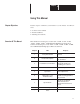
Chapter A–B 1 Using This Manual Chapter Objectives Read this chapter to familiarize yourself with the rest of the manual. You will learn about: • • • Overview Of This Manual Contents of the manual. Intended audience. Warnings and cautions. This manual is for Catalog Nos. 2755–L7SA, –L7SB, –L7SC, –L7SD, –L7RA, –L7RB, –L7RC, –L7RD Industrial Medium–Speed Bar Code Scanners and Catalog Nos. 2755–L9SA, –L9SB, –L9SD, –L9RA, –L9RB, and –L9RD Industrial High–Speed Bar Code Scanners.
Chapter 1 Using this Manual Intended Audience No special knowledge is needed to read this manual and follow its directions. If the system will be used to communicate with a higher level controller, we assume you are familiar with communication terminology. Warnings And Cautions Both warnings and cautions are found in this manual and on the equipment. The following symbols are used: CAUTION: This laser caution symbol appears where laser radiation is present.
Chapter 1 Using this Manual Figure 1.
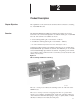
Chapter A–B 2 Product Description Chapter Objectives The capabilities of the scan head are described when connected to a Catalog No. 2755–DM9 Decoder. Overview The Industrial Medium and High Speed Bar Code Scanners are moving beam, bar code scan heads designed for use with the Catalog No. 2755–DM9 Decoder. The scanners are available as shown: • • Side scanning (Catalog No. 2755–L7Sx①, –L9Sx①) Side Raster scanning (Catalog No.
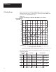
Chapter 2 Product Description L7 Reading Ranges Figure 2.2 illustrates the average reading ranges, relative to the symbol’s minimum bar width, that you should expect when using an L7 scanner with your Catalog No. 2755–DM9 Decoder. Figure 2.2 Average Scan Range vs. Minimum Bar Width for L7 Scanner Minimum Bar Width Mils 50 Millimeters 1.27 45 1.14 40 1.02 35 .89 30 .76 25 .64 2755–L7SC 2755–L7RC 20 .51 15 .38 2755–L7SD 2755–L7RD 10 .25 2755–L7SB 2755–L7RB 5 .
Chapter 2 Product Description L9 Reading Ranges Figure 2.3 illustrates the average reading ranges, relative to the symbol’s minimum bar width, that you should expect when using an L9 scanner with your Catalog No. 2755–DM9 Decoder. Figure 2.3 Average Scan Range vs. Minimum Bar Width for L9 Scanner Minimum Bar Width Mils 35 Millimeters .89 30 .76 25 .64 20 .51 2755–L9SD 2755–L9RD 15 .38 10 .25 2755–L9SB 2755–L9RB 2755–L9SA 2755–L9RA 5 .13 10 25.4 Inches 5 Centimeters 12.7 15 38.1 20 50.8 25 63.
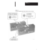
Chapter 2 Product Description Features Laser Shut Off – Use this switch to enable/disable the laser beam without interrupting power. The upward position (ON) enables the laser, the downward position (OFF) disables the laser beam. The use of this feature is covered in Chapter 5, Operation. LED indicators – There are two LEDs on the back of the scan head, Power On and Valid Read. They are defined in Figure 2.4. Figure 2.
Chapter 2 Product Description Figure 2.5 Scan Head Features Cabling Scanner to Decoder cables are sold separately. Refer to Table 2.C for information necessary to order the proper cable. Accessories Several accessories are available to provide installation and operational flexibility, including: • • • Package Detector Assembly – This assembly consists of a Package Detector Switch and a reflector. This switch indicates to the decoder that a package is present.
Chapter 2 Product Description The following table lists system accessories. Catalog Number Item Description 2755–NP3 Long Range Package Detector Assembly An infrared photoelectric switch and reflector. For the detection of packages up to a maximum of 18 feet (5.5 m) away. 2755–NP5 Short Range Package Detector Assembly A visible red photoelectric switch and reflector. For the detection of packages up to a maximum 10 feet (3 m) away.
Chapter A–B 3 Installation Considerations Chapter Objectives The operation of the scan head is briefly described. In addition, the importance of proper symbol positioning and the effect pitch has upon a symbol is also discussed. How thw Scan Head Operates Inside the scan head is the laser, the lens and mirror system and the electronics. The laser generates a small, concentrated light beam that is focused and projected through a window.
Chapter 3 Installation Considerations Positioning the Symbols Correctly As the symbols move past the scan head, they must be correctly oriented. The laser’s line of light must cut through all the bars and spaces in one sweep. Laser’s line of light cuts through the entire symbol For example, if the scan head is mounted so the laser beam is in the vertical direction, then the symbol must also be mounted vertically, commonly known as the step ladder orientation. Figure 3.
Chapter 3 Installation Considerations When setting up your scanner, you should attempt to have the laser line of light nearly perpendicular to the bars and spaces of the symbol. For optimal performance mount the scan head in a skewed position, 10° to 20° angle off normal from the symbol, as shown in Figure 3.4. Figure 3.
Chapter 3 Installation Considerations Figure 3.5 Positioning Terminology Skewed package and symbol Pitched package and symbol Tilted, over square symbol Correctly positioned symbol and package When setting up a raster scanner, the raster pattern can either overlap the entire symbol, or be restricted to cover only a portion of the symbol. Overlapping the symbol helps to aid in the scanning of misaligned symbols. Restricting, or dithering the raster pattern is helpful when scanning symbols of poor quality.
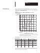
Chapter 3 Installation Considerations Usable Beam Length Figure 3.7 shows the size and shape of the scanning window. The black area is a no read are area. The Usable Beam Length (bottom of chart) is compared to the the Reading Distance (top of chart). The Usable Beam Length is slightly less than the projected beam length. The reading distance is measured from the scan window to the center of the symbol. Figure 7 Usable Beam Length Inches 0 0 Centimeters L7 Reading Distance① 5 12.7 10 25.4 15 38.
Chapter 3 Installation Considerations Compensating for Pitched Symbols When attempting to read a symbol that is pitched, two things must be considered: • • The adjusted minimum bar width The nearest and farthest code elements must be within the scanners reading range Minimum Bar with Adjustment When a symbol is pitched, the bars appear to be narrowerand closer to one another. This apparent element width is a reduction of the actual element width.
Chapter 3 Installation Considerations For example, a 21 mil (.53mm) symbol with 0° pitch can be successfully scanned at 27 inches (68.6 cm) with a Catalog. No. 2755–L7SC scanner. If you pitch the symbol 30° and determine the adjusted minimum bar width using the formula below, you will realize that you are attempting to read an 18 mil (.46 mm) symbol. Adjusted Minimum Bar Width = Actual Bar Width * cos [pitch angle] In our example, the following conditions apply: Actual Bar Width = 21 mil (.
Chapter 3 Installation Considerations Code Elelment Distance The pitched symbol’s nearest and farthest elements must be within the minimum and maximum reading distance of your scanner. Centering your symbol within the scanner’s minimum and maximum scan range can help guard against pitched symbols exceeding the scan range limits. However , you could exceed the scan range with a pitched symbol, as shown in Figures 3.10 and 3.11. Figure 3.10 Scan Range and Symbol Resolution at 0° Pitch 3” (7.
Chapter 3 Installation Considerations Figure 3.11 further illustrates how the pitched symbol changed the Scan Range enough to require a different scanner. Figure 3.11 Scan Range And Symbol Resolution Changed By Pitch 11.5 ” In this example, a 3 inch (7.6 cm) symbol pitched 30° will require the scanning beam to extend an additional 1.5 inches (3.8 cm). 10 ” 3” 2755–L7SA 1.5 ” Symbol’s Nearest Element 10” Symbol’s Farthest Element 11.5” Minimum Bar Width Mils 25 Millimeters .
Chapter A–B 4 Installation Chapter Objectives Carefully read this chapter before installing the system. We list rules and recommendations for installing and connecting your scanner. Warning and Cautions • ! • WARNING: Do not make any other adjustments to the equipment than those specified in this manual.
Chapter 4 Installation Determining the Space Requirements The decoder and scan head are separate units that can be mounted in different locations. A 10 foot (3 meter) or 25 foot (7.6 meter) cable is used to connect the two units. Figure 4.1 illustrates the dimensions of the scan head. Figure 4.1 Mounting Dimensions of the Scan Head 10–32UNF–2B x .31 2.69 in 6.83 cm 5.38 in 13.67 cm 2.69 in 6.83 cm Back View 2.20 in 4.75 in 3.00 in 4.75 in 12.07 cm 7.62 cm 12.07 cm Front View 5.59 cm 3.
Chapter 4 Installation Vibration Cautions The raster scanning models may occasionally experience raster rollover. This condition is caused by jarring the scanner, excessive vibration, and will occasionally occur upon power up. The stepping of the raster motor is controlled by an incremental shaft encoder, which has the ability to reset itself if one of the above conditions is met. Note: If the scanner is jarred during operation, labels may not be scanned while the raster is resetting.
Chapter 4 Installation How to Install the Swivel Mounting Base (Catalog No. 2755-NM1 and 2755-NM2) For greater installation flexibility, you can attach the scan head to an optional Swivel Mounting Base. The installation dimensions of the Swivel Base and its associated “T” Mounting Plate are shown in Figure 4.2. Figure 4.2 Mounting Dimensions of Swivel and “T” Mounting Plate Inches (Centimeters) 3.19 (8.10) 2.812 (7.14) .19 (4.83) .30 (7.62) 2.00 (5.08) 1.500 (3.81) 1.625 (4.13) .38 (9.65) 1.88 (4.
Chapter 4 Installation Using the Flat Mounting Plate (Catlaog No. 2755-NM3 Series B) A Flat Mounting Plate is also available. By attaching this plate to the bottom of your scan head, you can position the swivel mounting ball close to the base of the scan head. Make sure the Allen nut on the mounting ball is tight. You may also use the Flat Mounting Plate when you want to mount the scan head with brackets of your own design. Whenever possible, mount the scanner on its wide side as shown on page 4–3.
Chapter 4 Installation Installing the Package Detector Assembly When installing the Package Detector Assembly, we recommend you observe the following guidelines: • • • Install the Package Detector Switch at an angle to the label to minimize the light reflecting off the label. Install the reflector so the Package Detector’s operating range is not exceeded. The Package Detector’s beam must be broken before the label is in position. Figure 4.4 Recommended Placement of Package Detector Switch and Reflector.
Chapter A–B 5 Operation Chapter Objectives Guidelines on how to operate the scanners are described when connected to a Catalog Number 2755-DM9 Decoder. Warning and Cautions • ! • WARNING: Do not make any other adjustments to the equipment than those specified in this manual. WARNING: If at any time during operation an intense dot of light is generated instead of a thin line of light,immediately turn the laser off, using the toggle switch on the back of the scanner, then remove power to the decoder.
Chapter 5 Operation Scan Width Adjustment As shown in Figure 5.2, all scan heads come equipped with a 4 position switch used for scan width adjustment. The switch is covered by a gasketed 1/4–20 screw. Figure 5.2 Scan Width Adjustment Switch To avoid an unnecessarily long beam, rotate this switch clockwise. The scan width will reduce from full to approximately 3/4, 1/2 and 1/4. Figure 5.3 shows the scan width relative to the switch position.
Chapter 5 Operation Scan Width Adjustment Procedure 1. Remove power to the scan head. In doing so, you will avoid harmful direct eye contact with the beam. 2. Remove the gasketed 1/4–20 screw to expose the scan width adjustment screw. 3. Using the adjustment tool provided with the scanner, carefully rotate the switch to the desired position. 4. Replace the gasketed 1/4–20 screw. 5. Apply power to the scan head.
Chapter 5 Operation This switch selects the number of steps, or increments, the raster motor makes. To reduce the number of steps, rotate this switch counterclockwise. The raster heights are shown, relative to the switch positions, in Figure 5.4. Figure 5.4 Raster Height Adjustment Switch Positions 30° Raster Sweep 8° Raster Sweep Raster Height Adjustment Procedure 15° Raster Sweep 3° Raster Sweep Factory Setting 1. Remove power to the scan head.
Chapter A–B 6 Maintenance and Troubleshooting Chapter Objectives Maintenance procedures are stated and troubleshooting charts are provided in this chapter. Maintaining the Equipment ! Scan Window Removal WARNING: No user maintenance of the scan head is required. Do not open the enclosure. The scan window fits into an opening on the side of the scan head. A gasketed cover is then tightly secured over the window to ensure a NEMA 4 rating. To remove the scan window: 1.
Chapter 6 Maintenance and Troubleshooting Cleaning the Glass Window Do not use abrasive materials, such as disposable paperwipes, to clean the glass scan window. Most disposable wipes, or paper towels, use glass fibers which will scratch and cloud the window. Instead, use the following materials: Air: Optics rated clean air Solvent: Optics rated cleaning solution for use on coated lenses Wipe: Optics quality lens cleaning paper and cotton–tipped swabs.
Chapter 6 Maintenance and Troubleshooting Cleaning the Plastic Window Do not use abrasive materials, such as disposable paper wipes, to clean the plastic scan window. Most disposable wipes, or paper towels, use glass fibers which will scratch and cloud the window. Instead, use the following materials: Air: Optics rated clean air Solvent: Optics rated cleaning solution for use on coated lenses Wipe: Optics quality lens cleaning paper and cotton–tipped swabs.
Chapter 6 Maintenance and Troubleshooting Troubleshooting the System Problem Possible Solution Decoder is not turned ON. Turn decoder ON. Improper connection to power supply. Reconnect power cord to source. Line fuse on decoder is blown. Replace fuse on decoder. Faulty power cord or switch. Check that voltage is present at service outlet. No incoming power. Check that voltage is present at service outlet. Interconnect cable between decoder and scan head is loose.
Chapter A–B 7 Specifications Scan Head (Catalog Number 2755-L7 and L9 Electrical Receives power from decoder. Mechanical 10–32UNF–2B x .31 Enclosure Cast aluminum NEMA 4 LED Indicators Power On Valid Read Weight 6.5 lbs. (2.95 kg) Dimensions (H x W x D) 5.38” x 12.5” x 2.69” 2.69 in 6.83 cm 5.38 in 13.67 cm 2.69 in 6.83 cm Back View 2.20 in 4.75 in 3.00 in 4.75 in 12.07 cm 7.62 cm 12.07 cm Front View 5.59 cm 3.19 in 8.05 cm 10–32UNF–2B x .31 1.357 in 3.45 cm 2.69 in 6.83 cm 1.
Chapter 7 Specifications Optical Light Source Power Focused helium–neon (He–Ne) laser (632.8nm) 1.5 mW max. Fixed Scan Rate L7 – 350 scans/second, ± 5% L9 – 800 scans/second, ± 5% Scan sweep angle L7 47° L9 27° Scan Range L7 3.5” to 50” (8.89 cm to 127 cm) from scan window. ① L9 5” to 30” (12.7 cm to 76.2 cm) from scan window ① Depth of Field L7 3.5” to 50” (8.89 cm to 127 cm) from scan window ① L9 5” to 30” (12.7 cm to 76.
Glossary A–B G A AIM Acronym for Automatic Identification Manufacturers. alignment The relative position of a scanner or light source to the target or the receiving element. alphanumeric or alphameric The character set which contains letters, digits, and other characters such as punctuation marks. aspect ratio The ratio of height to width of a bar code symbol. A code twice as high as wide would have an aspect ratio of 2; a code twice as wide as high would have an aspect ratio of or 0.5.
Glossary bar length The bar dimension perpendicular to the bar width. bar width The thickness of a bar measured from the edge closest to the symbol’s start character to the trailing edge of the same bar. bidirectional symbol A bar code symbol that can be read in complementary (two) directions. binary code A power–of–two code; each bit position has a weighted value. bit An acronym for Binary Digit. The smallest unit of information in the binary numbering system. Represented by the digits 0 and 1.
Glossary clear area A clear space, containing no dark marks, that precedes the start character of a symbol and follows the stop character. That region of a document reserved for OCR characters and the required clear space around these characters. code A set of rules governing how the bars and spaces of the symbol will represent characters and groups of characters. bar code. code medium The material used to construct a machine readable code. Such materials may be retroreflective or opaque.
Glossary diverging beam A beam of light that is optically controlled so the light extends in different directions from the source. E EAN Acronym for European Article Numbering System, the international standard bar code for retail food packages. edge error Irregularities with respect to the average edge of an element. element 1) A single binary position in a character. 2) Dimensionally the narrowest width in a character, bar or space.
Glossary helium neon laser The type of laser most commonly used in bar code scanners. Because the laser beam is bright red, bars must not be printed with red ink since they would be indistinguishable from the background. I incandescent light source Intense white light used to illuminate an object as it passes under a CCD camera. intercharacter gap The space between two adjacent bar code characters. For example, the white space between two characters in AIM USS–39.
Glossary misread A condition which occurs when the data output of a reader does not agree with the encoded data presented. See substitution error. module A group of elements.The term module is used by the Uniform Product Code Council in it descriptions of the UPC code. A module is the narrowest unit of measure in the code. A module may be “black” or “white”. Contiguous modules are used to form bars or spaces that are wider than one unit.
Glossary OCR–B An abbreviation commonly applied to the character set contained in ANSI Standard x3.49–1975. off–line Refers to devices that operate independently of a central processing unit. on–line An operation in which peripheral devices are connected directly to the computer central processor unit. opacity 1) The property of paper that minimizes the show through of printing from the back side or the next sheet.
Glossary pitch 1) Rotation of a code pattern about the X axis. 2) The normal distance between the centerline or adjacent characters. pre–printed symbol A symbol which is printed in advance of application either on a label or on the article to be identified. Print Contrast Signal (PCS) A measurement of contrast (brightness difference) between the bars and spaces of a symbol. A minimum PCS value is needed for a symbol to be scannable.
Glossary read A successful scan of a bar code symbol. reflectance The amount of light returned from an illuminated surface. reflectance, absolute The ratio of the total reflectance by a document to the total light incident on the document. reflectance, diffuse Reflected light whose angle of reflection varies from the angle of incidence of the illuminating light; such as reflection from a non–glossy surface.
Glossary scanning curtain The effective reading area (width x height) of a moving beam scanner, which is equal to its depth–of–field and height–of– scan at a specific operating range. scanning range The combined distance of optical throw and depth of field. self–checking A bar code or symbol using a checking algorithm which can be applied to each character to guard against undetected errors. Non–self–checked codes may employ a check digit or other redundancy in addition to the data message.
Glossary substitution error This error can be seen in a mis–encodation, mis–read, or human operator error. Characters are substituted with erroneous information. Example: correct data is 1, 2, 3; substitution is 1, 2, 5. Substitution errors are usually the result of bar code labels with printing defects. Substitution errors are extremely difficult to determine and are usually not found until the data has been processed and an obvious data error is noticed.
Glossary valid read indicator An indicator on the: scan head that indicates a scan has been processed by the decoder and at least one label has been read. decoder that indicates a processed scan meets the capture count and fields per scan for at least one label. output module that indicates a processed scan meets the capture count, fields per package, and fields per scan for at least one label. void(s) The absence of ink within printed bars. The absence of ink within the confines of a character.
Index A–B A Abrasive materials on scan windows 6-2–6-3 Accessories 2-6–2-7 Alignment, symbol 3-3, G-2, G-6 Aluminum case 2-4, 6-1 Ambient temperature 7-1 Apparent bar width 3-3, 3-6, 5-4 Anti-reflective scan window 2-7 Attaching mounting plates 4-5 B Ball, mounting 2-6–2-7, 4-5 Beam width, usable 3-5, 5-2, G-3 Brackets 2-7, 4-3, 4-5 C Cabling 2-6 Caution 1-1–1-3, 4-1, 4-4, 5-1, 5-4, 6-2–6-3 CDRH 6-1 Centering label within scan range 3-8 Clearance, cable 4-3 Compensating for pitched symbols 3-6 Connector
Index rollover 4-4, 5-4, G-9 Reading Distance 3-5 Replaceable windows 2-4–2-6 Reset 4-4 Resolution 3-9, G-7–G-8 Rollover, raster 4-4, 5-4, G-9 S Scan angles 3-3, 4-3, G-7 range 2-2–2-3, 3-8–3-9, G-6, G-9 width adjustment 5-2 - 5-3 I–2 Scan Window 2-5, 6-1, 6-4 Cleaning 6-2–6-3 Removal/replacement 6-1–6-3 Skew 2-2–2-3, 3-3–3-4, 6-2, G-2, G-9 Solvents, use of 6-2–6-3 Specifications 7-1 Step Ladder position 3-2, G-5–G-6, G-10 Swivel mounting base 2-6–2-7, 4-3–4-5 T Terminology 1-2, 3-4 Toggle switch 3-3
Allen-Bradley has been helping its customers improve productivity and quality for 90 years. A-B designs, manufactures and supports a broad range of control and automation products worldwide. They include logic processors, power and motion control devices, man-machine interfaces and sensors. Allen-Bradley is a subsidiary of Rockwell International, one of the world’s leading technology companies. With major offices worldwide.