
Owner manual

4–6
Installing the Scanner
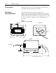
Use the following guidelines when installing the package detector.
• Mount the package detector and reflector so that the scan line
does not strike either of them.
• Install the reflector within the operating range of the package
detector.
• The package detector’s beam should be broken before the label is
in position. The package detect should remain active while the
entire symbol is within the scan line.
!
ATTENTION: The package detect cap or package
detector must be installed whenever the scanner is in
operation to maintain the NEMA Type 4 seal.
Removing the cap during scanner operation makes the
scanner susceptible to ESD damage.
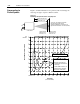
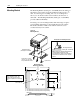
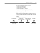
Figure 4.4
Recommended Placement of Package Detector and Reflector
Direction of Travel
Package Detector
Reflector
Scanner
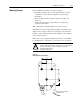
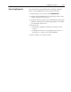
Table 4.A shows the connector pinout of the package detector cable
(attached to back of scanner). The package detector must be able to
operate using the +12V DC source (pin 1) and not draw more than
100mA. The package detect sense line (pin 2) must be able to sink
5mA at +12V DC.
Table 4.A
Pins Used on Package Detector Port
Package
Detect Port
Pin # Pin Function Wire Color
Face View Female
1 +12V DC Brown
Fa e Vew Female
➂
➁
2
➀
Package Detector Sense White
➀
➃
➂
➁
3 Ground Blue
➃
4 No Connection
(internally pulled up to 12V DC)
Black
➀
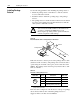
Triggers
the decoder to start decoding. The trigger active LED on the decoder lights when the
package detect input is active.
If the decoder is configured to turn the laser on only upon a package
detect, the laser will not turn on until the package detector is
triggered. Refer to the Decoder User Manual.
Installing Package
Detector