G–1 Allen-Bradley High Performance Visible Laser Diode Scanner (Cat. No.
Important User Information Because of the variety of uses for the products described in this publication, those responsible for the application and use of this control equipment must satisfy themselves that all necessary steps have been taken to assure that each application and use meets all performance and safety requirements, including any applicable laws, regulations, codes and standards.
Table of Contents Using this Manual Chapter 1 Chapter Objectives . . . . . . . . . . . . . . . . . . . . . . . . . . . . . . . . . . . What You Need to Know . . . . . . . . . . . . . . . . . . . . . . . . . . . . . . . Contents of Manual . . . . . . . . . . . . . . . . . . . . . . . . . . . . . . . . . . . Terminology . . . . . . . . . . . . . . . . . . . . . . . . . . . . . . . . . . . . . . . . European Union Directive Compliance . . . . . . . . . . . . . . . . . . . . . . Laser Warning Symbol . . . . .
ii Table of Contents – High Performance Visible Laser Diode User Manual Installing the Scanner Chapter 4 Chapter Objectives . . . . . . . . . . . . . . . . . . . . . . . . . . . . . . . . . . . Warnings and Cautions . . . . . . . . . . . . . . . . . . . . . . . . . . . . . . . . Tools You Need . . . . . . . . . . . . . . . . . . . . . . . . . . . . . . . . . . . . . . Determining Space Requirements . . . . . . . . . . . . . . . . . . . . . . . . . Mounting Scanner . . . . . . . . . . . . . . . . . . . .
Table of Contents – High Performance Visible Laser Diode User Manual iii Figures 2.1 2.2 2.3 3.1 3.2 3.3 3.4 3.5 3.6 3.7 3.8 3.9 3.10 3.11 3.12 3.13 4.1 4.2 4.3 4.4 5.1 5.2 6.1 Cabling Options . . . . . . . . . . . . . . . . . . . . . . . . . . . . . . . . . . . . . . Back of Scanner . . . . . . . . . . . . . . . . . . . . . . . . . . . . . . . . . . . . . Safety Labels . . . . . . . . . . . . . . . . . . . . . . . . . . . . . . . . . . . . . . . Picket Fence Orientation . . . . . . . . . . . . . . . .
Chapter 1 Using this Manual Chapter Objectives This chapter gives an overview of the manual, including: • contents of manual • what you need to know • conventions and terminology • European Union Directive Compliance • laser warning symbol • related publications What You Need to Know No special knowledge is required to read this manual or use the scanner. However, if using the scanner to communicate with a programmable controller or host device, you should be familiar with communication terminology.
1–2 Using this Manual Terminology This manual contains many terms that are used within the bar code industry and terms that are unique to the scanner. Refer to the glossary at any time for definitions of these terms. European Union Directive Compliance Refer to Appendix A for details on installing the scanner in industrial environments requiring compliance with European Union Directives. Laser Warning Symbol The following caution symbol is used where laser light is present.
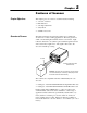
Chapter 2 Features of Scanner Chapter Objectives This chapter gives an overview of scanner features including: • overview of scanner • LED indicators • scan angle adjustment • safety labels • available accessories Overview of Scanner The high performance, fixed-mount scanners use a visible laser diode for non-contact scanning applications. The laser generates a small, concentrated light beam that exits the scan window.
2–2 Features of Scanner Overview of Scanner The scanners feature two scan rates, multiple read ranges and a NEMA Type 1 or NEMA Type 4 connector. Catalog Number Description 2755-LD4z1➀ 200 scans per second, NEMA Type 1 Connector 2755-LD4z4➀ 200 scans per second, NEMA Type 4 Connector 2755-LD8z1➁ 500 scans per second, NEMA Type 1 Connector 2755-LD8z4➁ 500 scans per second, NEMA Type 4 Connector ➀ z = A, B, C or E read range for LD4 scanners. See Figure 3.5.
Features of Scanner 2–3 Figure 2.2 Back of Scanner VALID POWER Scanner to Decoder Cable SCAN 6 LED Indicators Scan Angle Adjustment Seal Screw Package Detector Cable LED Indicators The back of the scanner (Figure 2.2) has two LED Indicators: VALID and POWER. These LEDs provide a visual indication of scanner operation. Table 2.A defines the color and function of each LED. Table 2.
2–4 Features of Scanner Safety Labels The scanners use a low power visible laser diode. As with any bright light source, such as the sun, you should avoid staring directly into the beam. Momentary exposure to a CDRH Class II laser is not known to be harmful. Figure 2.3 shows the location of all scanner safety labels. Figure 2.3 Safety Labels or AVOID EXPOSURE LASER LIGHT EMITTED FROM THIS APERTURE CAUTION DANGER LASER LIGHT – DO NOT STARE INTO BEAM 660 nm LASER LIGHT – 1.
Features of Scanner Accessories 2–5 Extension cables and replacement windows are available for each of the scanners. Scanner Extension Cables Each scanner has a permanently attached 10 foot (3 meter) cable which attaches to the decoder. Extension cables are available to increase the distance between the scanner and decoder to 25 or 50 feet (7.6 or 15.2 meters). Table 2.B lists the extension cables. Table 2.B Optional Scanner Extension Cables Description Catalog Numbers 2755-C15D1 15 feet (4.
2–6 Features of Scanner Mounting Bracket A mounting bracket (Cat. No. 2755-NM6) lets you mount the scanner on most flat surfaces. The bracket can be used with or without the optional Mounting Bracket Kit (Cat. No. 2755-NM42). Mounting Bracket (Catalog No. 2755-NM6) Mounting Bracket Kit (Catalog No. 2755-NM42) Replacement Windows Customer installed plastic and glass replacement windows are available for the scanners. To order replacement windows, refer to Table 2.C. Table 2.
Chapter 3 Installation Considerations Chapter Objectives This chapter provides information relevant to the installation and set up of the scanner including: • • • • • • proper positioning of bar code symbols read ranges usable beam length calculating minimum scans/symbol compensating for pitched symbols code element distance
3–2 Installation Considerations Positioning Symbols Correctly Bar code symbols must be in the correct orientation as they move by the scanner. The scan line must cross every bar, space and quiet zone on the symbol in one sweep. The orientation of the bar code symbol can be picket fence or step ladder. The orientation is determined by the symbol’s direction of travel relative to the scan line, not the horizontal or vertical orientation of the symbol. Figure 3.
Installation Considerations 3–3 Symbols that are pitched or tilted 45° are still readable. Skewed symbols can also be read as long as the misalignment is less than 50°. Figure 3.3 shows a correctly placed symbol and misaligned symbols.➀ Figure 3.3 Positioning Terminology Pitched package and symbol Skewed package and symbol Tilted, over square symbol Correctly positioned symbol and package Set up the scanner so the laser beam is nearly perpendicular to the bars and spaces of the symbol.
3–4 Installation Considerations 2755-LD4 Read Ranges The LD4 scanners can read bar code labels at various distances depending on the apparent minimum element width➀ and scanner to label pitch. The scanner can read labels within one of four read ranges: A, B, C or E. Figure 3.5 shows the reading distances for each range of the LD4 scanner. Table 3.A lists the read ranges for the LD4 scanners in numeric format. Refer to ”Compensating for Pitched Symbols” if your labels are pitched. Figure 3.
Installation Considerations 3–5 Table 3.A LD4 Read Ranges ➀ Minimum Element Width ➁ Mils Millimeters Read Range Inches Centimeters 4 5 7.5 10 13 20 30 6 7.5 10 13 20 30 35 9 10 13 20 30 35 40 50 .10 .13 .19 .25 .33 .51 .76 .15 .19 .25 .38 .51 .76 .89 .23 .25 .38 .51 .76 .89 1.02 1.27 4.0 - 5.25 3.0 - 6.0 2.5 - 6.5 2.5 - 7.25 2.5 - 8.0 2.5 - 9.75 2.5 - 12.0 8.0 - 11.5 7.25 - 12.75 6.25 - 14.5 5.0 - 16.0 5.0 - 19.0 5.0 - 19.0 5.0 - 19.0 14 - 21.0 13.25 - 22.75 10.75 - 28.25 7.5 - 36.0 6.0 - 42.25 6.
3–6 Installation Considerations 2755-LD4 Usable Beam Length Figures 3.6 and 3.7 show the Usable Beam Length versus Distance for the LD4 scanners. The black area is a no read area. The Usable Beam Length (bottom of chart) is compared to the Reading Distance (top of chart). The Usable Beam Length is approximately 20% less than the projected beam length (10% on each end of the scan line). The reading distance is measured from the scan window to the center of the symbol. (A,B,C Ranges) Figure 3.
Installation Considerations 2755-LD4 Usable Beam Length 3–7 Figure 3.7 LD4E Usable Beam Length ➀ (E Range) LD4E Reading Distance ➁ Inches Centimeters NA NA 5 12.7 10 25.4 15 38.1 20 50.8 25 63.5 30 76.2 35 88.9 40 101.6 45 114.3 50 127.0 55 139.7 60 152.4 65 165.1 70 177.8 75 190.5 80 203.2 85 215.9 Usable Beam Length Reading Distance = Catalog No. 2755–LD4E = No Read Area Inches Centimeters NA NA 6.7 17.0 9.4 23.8 12.1 30.6 14.7 37.4 17.4 44.2 20.1 51.1 22.8 57.9 25.
3–8 Installation Considerations 2755-LD8 Read Ranges The LD8 scanners can read bar code labels at various distances depending on the apparent minimum element width① and scanner to label pitch. The scanner can read labels within one of three read ranges: A, B, or C. Figure 3.8 shows the reading distances for each range of the LD8 scanner. Table 3.B lists the read ranges for the LD8 scanners in numeric format. Refer to ”Compensating for Pitched Symbols” if your labels are pitched. Figure 3.
Installation Considerations 3–9 Table 3.B LD8 Read Ranges ➀ Minimum Element Width ➁ Mils Millimeters 4 5 7.5 10 13 20 30 6 7.5 10 13 20 30 35 9 10 13 20 30 35 40 50 .10 .15 .19 .25 .33 .51 .76 .15 .19 .25 .33 .51 .76 .89 .23 .25 .38 .51 .76 .89 1.02 1.27 Inches 3.5 3.25 2.75 2.75 2.5 3.25 5.25 7.0 7.0 6.75 6.75 6.75 6.0 5.5 14.5 14.25 13.75 12.75 11.0 10.0 10.0 10.0 - Read Range Centimeters 4.5 5.5 6.25 6.75 7.5 9.25 10.25 11.75 12.5 14.0 16.0 20.0 20.0 20.0 19.5 22.75 26.75 36.0 41.75 44.5 47.5 50.
3–10 Installation Considerations 2755-LD8 Usable Beam Length Figure 3.9 shows the Usable Beam Length versus Distance for the LD8 scanner. The black area is a no read area. The Usable Beam Length (bottom of chart) is compared to the Reading Distance (top of chart). The Usable Beam Length is approximately 20% less than the projected beam length (10% on each end of the scan line). The reading distance is measured from the scan window to the center of the symbol. Figure 3.
Installation Considerations Calculating Scans/Symbol 3–11 This section explains how to calculate minimum scans per symbol for picket fence and step ladder applications.
3–12 Installation Considerations Calculating Scans/Symbol Example 2: Increasing the conveyor speed in Example 1 to 300 ft/min. decreases the number of scans per symbol to less than 3. This means the 2755-LD4C1 scanner is no longer appropriate.
Installation Considerations 3–13 Step Ladder Applications To calculate minimum scans per symbol for step ladder applications, use this formula: S = S A H Z = = = = AxH Z Scans per Symbol (must be at least 5) Derated Scan Rate (nominal scan rate – 5%) Symbol Height (length of bars of symbol) Conveyor Speed Conveyor Speed and Symbol Height must be expressed in similar units.
3–14 Installation Considerations Calculating Scans/Symbol Example 2: Increasing the conveyor speed in Example 1 to 300 ft/min. decreases the minimum number of scans per symbol to approximately 3. This value is below the recommended value of 5 scans per symbol making the 2755-LD4C1 inappropriate. The label would have to be at least 1.6 inches tall to be read by an LD4C1 scanner.
Installation Considerations Compensating for Pitched Symbols 3–15 You must consider the following when reading symbols that are pitched: • The apparent minimum element width • The nearest and farthest code elements must be within the scanner’s read range. Determining Apparent Minimum Element Width When a symbol is pitched, the bars appear to be narrower and closer to one another. This apparent element width is a reduction of the actual element width.
3–16 Installation Considerations Compensating for Pitched Symbols For example, a 10 mil (0.25 mm) symbol with 0_ pitch can be scanned at 17 inches (43.2 cm) with a Catalog No. 2755-LD8C1 scanner. If you pitch the symbol 30_ and determine the apparent minimum element width using the formula below, the apparent element width is 8.6 mils (0.22 mm).
Installation Considerations 3–17 Code Element Distance The nearest and farthest elements of a pitched symbol must be within the minimum and maximum reading distance of the scanner. Centering the symbol within the scanner’s read range helps to prevent pitched symbols from exceeding the read range limits. You can still exceed the read range with a pitched symbol, as shown in Figures 3.12 and 3.13. Figure 3.12 Read Range and Symbol Resolution at 0_ Pitch 18 inches (45.7 cm) 3 inch (7.
3–18 Installation Considerations Compensating for Pitched Symbols Figure 3.13 further illustrates how a pitched symbol can change the read range enough to require a different scanner. Figure 3.13 Read Range and Symbol Resolution Changed By Pitch 19.5 Inches (49.5 cm) 18 Inches (45.7 cm) 3 inch (7.6 cm) symbol is pitched 30°. This requires the read range to extend an additional 1.5 inches (3.8 cm). Apparent element width = 17.
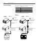
Chapter 4 Installing the Scanner Chapter Objectives This chapter provides guidelines and recommendations on how to install and connect your scanner including; • Space Requirements • Mounting Scanner • Connecting Equipment • Installing Package Detector Warnings and Cautions ! ! ! ATTENTION: No user maintenance of the hardware is required. Do not make adjustments to the scanner other than those specified in this manual and do not open the scanner housing.
4–2 Installing the Scanner Tools You Need Typically, the only tool you need for installation is the adjustment tool supplied with the scanner and a screwdriver. Determining Space Requirements The scanner and decoder are mounted separately. The scanner-to-decoder cable is 10 feet (3.0 meters) long. The scanner to package detect cable is approximately 11.5 inches (.29 meters) long. Extension cables increase the scanner-to-decoder distance to 25 or 50 feet (7.6 or 15.2 meters). Figure 4.
Installing the Scanner Mounting Scanner 4–3 Before installing the scanner, review the following: • Determine optimum position of the scanner relative to the bar code labels to be read. Refer to Chapter 3 for positioning information. • Allow adequate clearance at back of scanner for cables. See Figure 4.1. • Securely mount scanner to a rigid surface to ensure proper operation of the scanner. Note: If using the mounting bracket, refer to the next page.
4–4 Installing the Scanner Mounting Bracket The Mounting Bracket (Catalog No. 2755-NM6) allows mounting on flat surfaces. The scanner is supplied with three #10-32 screws (1/2 inch, 12.7 mm long) for mounting. Two sets of mounting holes allow you to mount the scanner to the bracket as shown below or turned 90_. The Mounting Bracket Kit (Catalog No. 2755-NM42) provides additional flexibility.
Installing the Scanner Connecting Equipment 4–5 Use the steps below as a guideline when connecting equipment. Refer to the User Manual for your decoder when necessary. 1. Verify that the power to the decoder is TURNED OFF. 2. Connect optional package detector to the package detector cable on back of scanner. See next section. 3. Connect the scanner to the decoder by attaching the scanner cable (with the connected extension cable if appropriate) to the scanner port on the back of the decoder. 4.
4–6 Installing the Scanner Installing Package Detector Use the following guidelines when installing the package detector. • Mount the package detector and reflector so that the scan line does not strike either of them. • Install the reflector within the operating range of the package detector. • The package detector’s beam should be broken before the label is in position. The package detect should remain active while the entire symbol is within the scan line.
Chapter 5 Operating the Scanner Chapter Objectives This chapter provides information on how to operate the scanner when connected to a decoder. Warnings and Cautions ! ! ATTENTION: Do not make any adjustments to the scanner other than those specified in this manual. ATTENTION: If during operation an intense dot of light is generated instead of a thin line of light, immediately turn the laser off via the decoder configuration software, and then remove power from decoder.
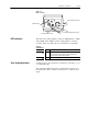
5–2 Operating the Scanner Scan Angle Adjustment Each scanner has a multi-position rotary switch which lets you adjust the scan angle ∠ to !@2, #@4, or maximum angle. Catalog No. 2755-LD4 A,B,C Setting !@2 #@4 MAX Nominal Scan Angle 25_ Catalog No. 2755-LD4 E Catalog No. 2755-LD8 Setting Setting 37.5_ !@2 #@4 50_ MAX Nominal Scan Angle 20_ 30_ !@2 #@4 40_ MAX Nominal Scan Angle 15_ 22.
Operating the Scanner 5–3 The scan angle adjustment switch has 4 positions: • Position #1 is full scan angle • Position #2 is 3/4 scan angle • Position #3 and #4 is 1/2 scan angle To avoid an unnecessarily long scan, rotate this switch counterclockwise. The scan angle will reduce from full to approximately #@4, and !@2. Figure 5.2 shows the scan angle relative to the switch position. In each case, the usable beam will be approximately 80% of the actual beam width. Figure 5.
Chapter 6 Maintenance and Troubleshooting Chapter Objectives This chapter provides troubleshooting information to assist with problem detection and resolution. It also describes how to remove the scan window for cleaning or to replace the window. Maintenance of Scanner ! Cleaning Scan Window ATTENTION: No user maintenance of the scanner is required. Do not open the enclosure! Removing or attempting to remove sealed screws will void the warranty.
6–2 Maintenance and Troubleshooting Replacing Scan Window The scan window fits into an opening behind the front of the scanner. A bezel and gasket create a NEMA Type 4 seal. The table below lists replacement numbers for ordering a glass or plastic window kit. Do not substitute other material for a damaged window. The windows have an optical coating necessary to scanner performance.
Maintenance and Troubleshooting Troubleshooting 6–3 This section lists problems that may occur with the scanner and/or connected decoder. Each problem lists possible causes and solutions. Problem: “Power” indicator on both the scanner and decoder do not light. Cause: Solution: Cause: Solution: No incoming power. Verify power source. Cause: Solution: Improper connection to power source. Check connections. Cause: Faulty decoder. Return decoder to Allen-Bradley for repair.
6–4 Maintenance and Troubleshooting Problem: “Power” indicator lights but the laser beam is not on. Cause: Solution: Cause: Solution: Package detector not operating. Verify decoder configuration / package detect operation. Cause: Laser scanning mechanism is not operating correctly. Return scanner to Allen-Bradley for service. Solution: Problem: Decoder setup parameters are not set up properly. Verify decoder configuration. Unable to read a label. Cause: Solution: Decoder not configured correctly.
Chapter Specifications Electrical Receives power from decoder Mechanical Enclosure NEMA Type 4 Connectors NEMA Type 1 (Subminiature DB15) NEMA Type 4 (Cannon KPT Series) Package Detect NEMA Type 4 Micro-Mini Connector (Crouse-Hinds) NEMA Type 4 Micro-Change Connector (Brad Harrison) LED Indicators POWER ON Amber VALID READ Green Weight (Approximate) 4.0 lbs (1.8 kg) Dimensions Inches 3.1 (H) x 3.8 (W) x 4.5 (D) Millimeters 78.7 (H) x 96.5 (W) x 116.
7–2 Specifications Package Detect External, +12 V DC, @ 100 mA max.
Appendix A European Union Directive Compliance European Union Directive Compliance If this product is installed within the European Union or EEA regions and has the CE mark, the following regulations apply.
A–2 European Union Directive Compliance Declaration of Conformity
Glossary Glossary AIM Acronym for Automatic Identification Manufacturers. Alignment The relative position of a scanner or light source to the target of the receiving element. Alphanumeric The character set containing letters, numbers, punctuation marks, and symbols. Aspect Ratio The ratio of height to width of a bar code symbol. A code twice as high as wide would have an aspect ratio of 2; a code twice as wide as high would have an aspect ratio of !@2 or 0.5.
G–2 Glossary Character A single group of bars and spaces representing an individual number, letter or punctuation mark. A graphic shape representing a letter, number or symbol. Character Alignment The vertical or horizontal position of characters with respect to a given reference line. Character Density The dimension, in linear inches, required to encode one character. Character Set Those characters available for encoding purposes. Character Skew See skew.
Glossary G–3 Depth of Field The distance between the maximum and minimum reading distances where a symbol can be read. Diffuse Reflection Reflection of light in all directions. Diffuse reflection occurs from non-glossy surfaces. See specular reflection. Dirt In paper, refers to the presence of relatively non-reflective foreign particles embedded in the sheet. The size and lack of reflectance of the particles may cause the optical scanner to mistake the dirt for inked areas (i.e. paper noise).
G–4 Glossary Mis-encodation When the characters which were to be represented in symbol form are not correctly encoded. Example: desired number is 1, 2, 3, 4; the encoded number is 1, 2, 5, 4. Misread A condition which occurs when the data output of a decoder does not agree with the encoded data presented. See substitution error. Moving Beam Scanner A device which dynamically searches for a bar code pattern by sweeping a moving optical beam through a field of view.
Glossary G–5 Pitch 1) Rotation of a code pattern about the Y axis. 2) The normal distance between the centerline or adjacent characters. Pre-printed Symbol A symbol which is printed in advance of application either on a label or on the article to be identified. Print Contrast Signal (PCS) A measurement of contrast (brightness difference) between the bars and spaces of a symbol. A minimum PCS value is needed for a symbol to be scannable.
G–6 Glossary Resolution 1) The measure of the ability of a lens, a photographic material or a photographic system to distinguish detail under certain specific conditions. 2) The dimension of the smallest element which can be printed employing a particular technique. 3) The narrowest element dimension which can be distinguished by a particular reading device. Retroflective Characteristics of material causing it to reflect light back to its source regardless of angle of incidence.
Glossary G–7 Spectral Response The variation in sensitivity of a device to light of different wavelengths. Specular Reflection Reflection of light from a surface at an angle equal but opposite to the angle of incidence. See reflectance, specular. Spots Ink or dirt spots within the spaces or clear area of a bar code which may reduce first read rate. Start/Stop Characters Bar code characters that provide the scanner with information on the how the code is bounded and its orientation.
G–8 Glossary Void The absence of ink within printed bars. The absence of ink within the confines of a character. White Zone See quiet zone.
Rockwell Automation helps its customers receive a superior return on their investment by bringing together leading brands in industrial automation, creating a broad spectrum of easy-to-integrate products. These are supported by local technical resources available worldwide, a global network of system solutions providers, and the advanced technology resources of Rockwell. Worldwide representation.