
User Manual


4–3Installing the Decoder
Publication 2755-833
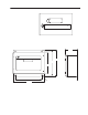
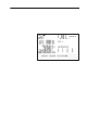
Figure 4.1 View of the front cover from inside
Pull on tab to remove LED Label insert
LCD Display
(optional)
LED Board
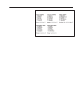
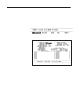
Figure 4.2 shows nominal mounting dimensions in inches (and cm)
for the NEMA Type 1 and Type 4 decoders. The horizontal mounting
orientation is shown here.
Figure 4.2 Mounting dimensions (for reference only)
10.25 in
(26.0 cm)
9.5 in
(24.1 cm)
8.0 in
(20.3 cm)
12.0 in
(30.5 cm)
ALLEN-BRADLEY
4.6 in
(11.7 cm)
Mounting
Holes
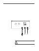
Allow clearance of 6 inches above and below decoder for cables
10.5 in
(26.7 cm)
You can mount the decoder horizontally or vertically. When
mounting allow clearance:
• at hinged side of cover for cover to swing open
• of 6 inches (152 mm) above the decoder to connect cables to the
scanner ports and communication ports
Mounting the Decoder