
User Manual


16–3PCCC Host Commands
Publication 2755-833
• STS
Byte 1 specifies the command status which is always 0.
• TNS
Bytes 2 and 3 contain a unique transaction number sequence that
links each command to a reply
. The TNS is user defined.
• FNC Code
When the CMD byte = 06H (diagnostic command), byte 4
specifies a diagnostic function. For example, FNC = 01 means
read diagnostic counters.
• Low Address
When the CMD byte = 01H (unprotected read command) or 08H
(unprotected write command
) byte 4 contains the low byte of a
two byte address.
The low address (byte 4) and high address (byte 5) map to a
specific area in decoder memory for a read or write operation.
• High Address
When the CMD byte = 01H (unprotected read command) or 08H
(unprotected write command
) byte 5 contains the high byte of a
two byte address.
The low address (byte 4) and high address (byte 5) map to a
specific area in decoder memory for a read or write operation.
• Data
The data area is command dependent. The starting byte for the
data area is also command dependent.
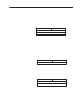
Command Reply Format
The general format and definition of a command reply is:
0STS CMD Reply
TNS
Data 124 bytes maximum
H
i
gh
Byt
eL
o
w
Byt
e
MSB LSB
1
32
4
.
.
.
126
5
.
.
.
127
Optional
• CMD Reply
Byte 0 contains the response to a command. Bit 6 is set for the
reply and responses are: