ALLEN-BRADLEY Bulletin 2755 High Speed Decoder (Catalog Numbers 2755-DM9 & -DM9E) User Manual
Important User Information Solid state equipment has operational characteristics differing from those of electromechanical equipment. “Safety Guidelines for the Application, Installation and Maintenance of Solid State Controls” (Publication SGI-1.1) describes some important differences between solid state equipment and hard–wired electromechanical devices.
Table of Contents A–B Using This Chapter Chapter 1 Chapter Objectives Overview of This Manual Intended Audience Conventions Used Warnings and Cautions Nomenclature Related Publications Description of Hardware Chapter 2 Chapter Objectives Differences Between DM9 and DM9E Features of the Decoder Laser Scan Heads Physical Description Indicators Communications Ports Output Modules Power and Scan Head Connectors Accessories How the Decoder Operates 2–1 2–1 2–1 2–2 2–2 2–3 2–5 2–6 2–8 2–9 Chapter 3 Chapte
Table of Contents Configuring Your Decoder Chapter 4 Setup Screen #1 Setup Screen #1 Fields Message Format Data Check Characters Host Communications Package Detect Input Setup Screen #2 Setup Screen #2 Fields Bar Code Types Code Lengths Scanner Control Match Code Table Outputs Input Programming Example Installing the Decoder Chapter 5 Chapter Objectives Equipment You Will Need Electrical Precautions How to Handle Excessive Noise Grounding Recommendations Determining Space Requirements Installing the Dec
Table of Contents Host Commands Using a RS-232 or RS-422 Interface Chapter 7 Chapter Objectives RS–232/RS–422 ASCII Command Protocol Single Character Commands Two Character Commands Responses to Commands Host Commands 1. Set Code 39, I 2–of–5, and Codabar Check Characters 2. Clear Output Counter 3. Enable/Disable Bar Code Type 4. Set Configuration to Default Values 5. Set Host Communications 6. Write Header Message 7. Set Package Detect Input Filter and Sense 8. Write Source Identification Message 9.
Table of Contents Unprotected Write Command Unprotected Write Command Structure Unprotected Write Command Cont.
Table of Contents Figures 2.1 2.2 2.3 2.4 2.5 Catalog No. 2755–DM9, –DM9E Decoder . . . . . . . . . . . . . . . . . . . . LED Indicators ... Communications Ports ... Output Modules ... Input power and Scan Head Connectors ... 2–3 2–4 2–5 2–6 2–8 3.1 3.2 3.3 3.4 3.5 3.6 Catalog No. 2755–DM9, –DM9E Decoder DC Output Module Application AC Output Module Application Input Module Auto Load Application Communications Interface Examples Decoder Memory ... ... ... ... ... ... 3–1 3–3 3–3 3–4 3–5 3–8 4.
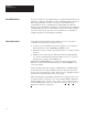
Chapter A–B 1 Using This Manual Chapter Objectives Read this chapter to familiarize yourself with the rest of the manual. You will learn about: • • • • Overview of this Manual Contents of the manual. Intended audience. Conventions useed. Warnings and cautions. This manual describes how to use the Catalog No. 2755–DM9 and DM9E High Speed Decoders. This manual contains the following chapters: Chapter Title Purpose 1 Using This Manual Provides an overview of the manual.
Chapter 1 Using this Manual Intended Audience You do not require any special knowledge to read this manual and follow its instructions. If the decoder will be used to communicate with a computer or PLC TM programmable controller, we assume you are familiar with communication devices, communications standards (RS–232, RS–422, RS–485), and communications terminology. In this manual, we describe the commands that a host device can transmit to the decoder and the command responses sent by the decoder.
Chapter 1 Using this Manual Warnings And Cautions Both warnings and cautions are found in this manual and on the equipment. The following symbols are used: WARNING: A warning symbol means people might be injured if the procedures are not followed. CAUTION: A caution symbol is used when machinery could be damaged if the procedures are not followed. Nomenclature Related Publications This manual may contain some terms that you are not familiar with.
Chapter A–B 2 Description of Hardware Chapter Objectives This chapter provides an overview of the Catalog Number 2755-DM9, -DM9E Bar Code Decoder. We also provide descriptions of the major features. Note: In this chapter and in subsequent chapters, we will refer to the Catalog Number 2755-DM9, -DM9E High Speed Decoder as the decoder. Differences between Catalog Number 2755-DM9 & 2755-DM9E • • Catalog Number 2755-DM9 decoder includes a 120 VAC power cord, and an English language manual.
Chapter 2 Description of Hardware You can program many of the operating parameters of the decoder. This programming capability allows you to adapt the decoder to a specific application. You can: • • • • • • Specify decoder operating modes. Select types and lengths of symbols to be read. Select communications protocols used when communicating with a computer or programmable controller. Enter up to eight match codes. Specify up to eight discrete outputs. Specify up to eight discrete outputs.
Chapter 2 Description of Hardware Figure 2.1 Catalog Number 2755-DM9, -DM9E 90-061-1 Indicators Fourteen LED indicators (Figure 2.2) provide an indication of the decoder status. The indicators provide the following indications: • • • POWER - This green indicator illuminates when power is applied to the decoder. LASER ON - This red indicator illuminates when the decoder has enabled the scan head to turn on the laser light source.
Chapter 2 Description of Hardware Note: This LED may not correspond to a read output condition (refer to page 4-41). In the triggered mode, the read output condition must meet the fields per package parameter. • CPU ACTIVE - This green indicator is continuously illuminated under normal operation. Failure of the CPU ACTIVE indicator to illuminate is an indication of a hardware failure.
Chapter 2 Description of Hardware Communications Ports There are two communication port connectors on the decoder: • HOST port connector. The HOST port connector supports RS-232, RS-422, and RS-485 communication interfaces. Through this port, you can link the decoder to a host computer or programmable controller. Both commands and data may be sent to/from the host device. Note: The RS-485 interface allows the decoder to be installed as part of a multi-drop network.
Chapter 2 Description of Hardware Output Modules Two DC output modules (Catalog No. 1781-OB5S) are provided with the decoder. You can add up to six more AC or DC output modules for a total of eight. Module location #8 can also accept an input module for auto loading match codes (refer to Chapters 3 and 4). All output module types can be installed in any of the eight module slots.
Chapter 2 Description of Hardware The following output modules are available. Note: Output modules function as a switch, not as a power source. Catalog No. 1781-0B5S 1781-0A5S 1781-OM5S -- 120 VAC 240 VAC Maximum Line Voltage 60 VDC 140 VAC 280 VAC Minimum Line Voltage 3.0 VDC 12 VAC 24 VAC Maximum Peak Off State Voltage 60 VDC 400 V Peak 600 V Peak Maximum Off-State Leakage 1.0 mA 2.5 mA RMS 4.0 mA RMS -- 200 V/ usec 200 V/ usec Maximum On-State Current 0.5 A DC 0.5 A RMS 0.
Chapter 2 Description of Hardware Power and Scan Head Connectors The decoder will accept line voltages from 85 to 264 volts AC at a frequency of 47 to 63 Hz without any adjustments. The Catalog No. 2755-DM9 decoder is supplied with a 120VAC rated power cord. If you are powering a 2755-DM9 decoder with a supply voltage greater than 120 VAC, you must obtain a suitable power cord. Note: Catalog No. 2755-DM9E is supplied with an unterminated power cord.
Chapter 2 Description of Hardware Accessories The following table lists the accessories that you may require for use with the decoder. Catalog Number Item Description Industrial Medium Speed Bar Code Scanner Raster and side scanning devices that operate at 350 scans per second. Raster scanners scan both vertical and horizontal directions simultaneously. Some of these scan heads have a maximum read distance of 50” (1.27 meters) depending upon symbol size and quality.
Chapter A–B 3 How the Decoder Operates Chapter Objectives This chapter provides a brief description of how the decoder operates. We also provide a brief description of how the decoder communicates with host devices. How the Decoder Operates Figure 3.1 is a block diagram of the decoder. Figure 3.
Chapter 3 How the Decoder Operates MICROPROCESSOR - The microprocessor reads the information obtained by the data acquisition circuit, processes the information, and then makes decisions on what to do with the decoded data based upon your programming instructions. I/O - A single 25 pin connector (HOST PORT) provides three different interfaces (RS-232, RS-422, and RS-485) for communications with a host computer or programmable controller.
Chapter 3 How the Decoder Operates AC Output Module Application Figure 3.3 illustrates a typical AC output module application. When using high impedance loads, you may have to add an additional resistor (Rx) in parallel with the load. Select a value for Rx that maintains a minimum current of 50 mA RMS through the output module in the on state. Figure 3.3 AC Output Module Application DECODER AC SOURCE CONNECTOR BLOCK AC OUTPUT MODULE FUSE LOAD Rx Input Module Auto Load Application Figure 3.
Chapter 3 How the Decoder Operates interfaces (RS-232, RS-422, and RS-485) provide a variety of ways to accomplish communications with a host. Figure 3.5 illustrates some of the possible host interfaces. Note: You can also use the decoder as a stand-alone device using the discrete outputs for control. Figure 3.
Chapter 3 How the Decoder Operates Figure 3.5 Communications Interface Examples (Continued) PLC TO DECODER USING AN ASCII MODULE PLC 1771 I/O Rack 1771-DA RS-232 2755-DM9 Decoder PLC TO DECODER USING A BASIC MODULE PLC 1771 I/O Rack 1771-DB RS-232 2755-DM9 Decoder COMPUTER TO DECODER Host Computer RS-232 or RS-422 2755-DM9 Decoder Catalog No. 1771-DB is a BASIC I/O Module Catalog No. 1771-DA is an ASCII I/O Module ALLEN-BRADLEY LOCAL-AREA NETWORK - Using the Catalog No.
Chapter 3 How the Decoder Operates RAM and EEPROM Memory Before you try to change the operating configuration of the decoder, you should understand how configuration parameters are stored. The decoder has two types of memory: • EEPROM- Electrically Erasable Programmable Read Only Memory contains the “non-volatile” operating configuration of the decoder. The term “non-volatile” means that the memory is not lost when you turn the power off or restart the decoder.
Chapter 3 How the Decoder Operates will become effective immediately (except for host communications parameters listed below). If you want to enter changes into the decoder’s permanent memory (EEPROM), you must use the SAVE command. When the decoder is restarted, the operating parameters of the EEPROM are transferred into RAM.
Chapter 3 How the Decoder Operates In the triggered mode of operation, there are three possible trigger sources: • • • Trigger Ending Coditions Host command - The command is generated by a host computer or programmable controller. Package detect - A package detector connected to the scan head is the source for the trigger. Internal timer - The internal timer cycles the trigger from on to off based on a timed interval.
Chapter A–B 4 Configuring Your Decoder Chapter Objectives Because the decoder can be used many ways, you will need to configure the decoder to meet the requirements of your application. To do this, you must make some decisions. We will show you how to use the menus and setup screens that appear on a programming terminal to select the options you need. Initial Programming of the Decoder You must configure the decoder to meet the requirements of the application.
Chapter 4 Configuring Your Decoder Programming Terminal Cable Programming of the decoder is done through the AUX connector on the back of the decoder. The AUX port connector on the decoder is a standard 25 pin, female, D type connector. Depending upon your programming terminal, most standard RS-232 communications cables will work. If you need to create a communications cable, refer to Appendix A.
Chapter 4 Configuring Your Decoder Step 2 - Turn the decoder ON. The green LEDs, labeled POWER ON and CPU ACTIVE, will light. Step 3 - When the following screen appears, press the key that corresponds to the language you are using. All of the remaining screens will appear in the selected language.
Chapter 4 Configuring Your Decoder Select Operation Menu After selecting the CRT type, the following Select Operation menu will appear: 2755-DM9 Bar Code Reader VX.XX Copyright 1990 Allen-Bradley Company, Inc.
Chapter 4 Configuring Your Decoder (Continued) 19876367 3456721 59874292 45763019 56474821 10945280 45674895 7689577 87599039 35426881 11987454 54664778 87997070 56400982 54664747 09585746 7563778 53647747 87745646 35647465 6545456 2) Display Status and Counters - After selecting this operation by pressing the [2] key at the select operations menu, the decoder will display the following: • Decoder Performance - The percentage of decodable scans over a 100 scan sample.
Chapter 4 Configuring Your Decoder specified by the fields per package configuration parameter. Data that is lost due to an overflow of the buffer does not increment this counter. • • Package Counter- The number of packages detected. This counter is incremented each time a package trigger is generated by the scan head package detector, a host command, or the internal timer. Output Counters 1 through 8 - The number of times an output condition has occurred.
Chapter 4 Configuring Your Decoder CAUTION Configuration changes may cause the discrete outputs to switch. If outputs are to remain ENABLED, press ESC. Otherwise press any other key to continue. Outputs will be DISABLED until the device is restarted. Note: We recommend that you disable the outputs while configuring the decoder. This will prevent the outputs from being turned on unintentionally during changes to the configuration.
Chapter 4 Configuring Your Decoder -- SYMBOLOGY -CODE 39: Yes I 2-OF-5: No CODE 128: No CODABAR: No UPC-A: No UPC-E: No EAN-8: No EAN-13: No -------- LENGTHS -------- -------- SCANNER CONTROL -------00 00 00 00 00 00 00 00 LASER-ON MODE: Continuous 00 00 00 00 00 00 00 00 DECODE TRIGGER: Package Detect 00 00 00 00 00 00 00 00 CAPTURE COUNT: 2 (scans) 00 00 00 00 00 00 00 00 FIELDS/SCAN: 1 FIELDS/PACKAGE: 1 NO-READ TIMER: 0000 (msec) INTER-SCAN TIMER: 0000 (msec) MATCH COMPLETE: 1 ---------MATCH CODE TABL
Chapter 4 Configuring Your Decoder RESTART SYSTEM . . . Confirm (Y/N) Press the [Y] key to confirm the restart. Pressing the [N] key will cancel the restart function.
Chapter 4 Configuring Your Decoder Depending upon the type of field (select or edit) that you are configuring, use the commands listed in Table 4.A: To do this: You must: Return to SELECT OPERATION menu. Comments Press the [ESC] key to select the command bar and then press the [ESC] key again. Change any field. Press [SPACE] bar. In select fields, next option is displayed. In edit fields, field is cleared and new data can be entered. Enter a new or different value. Press [RETURN] key.
Chapter 4 Configuring Your Decoder Type in the new data and press the [RETURN] key to close the field and enter the data. Note: Pressing the [ESC] key while you are entering data in an edit field will return the contents of the field back to the original contents prior to editing. When you enter a value in a field that requires an ASCII decimal value, you have three options: 1) You can enter the decimal (numeric) equivalent value (refer to Appendix C).
Chapter 4 Configuring Your Decoder ASCII Control Character Enter: ASCII Control Character Enter: ASCII Control Character Enter: NUL %@ VT %K SYN %V SOH %A FF %L ETB %W STX %B CR %M CAN %X ETX %C SO %N EM %Y EOT %D SI %O SUB %Z ENQ %E DLE %P ESC %[ ACK %F DC1 %Q FS %\ BEL %G DC2 %R GS %] BS %H DC3 %S RS %∧ HT %I DC4 %T US %_ LF %J NAK %U SELECT FIELDS- To change the contents of a select field, press the [SPACE] key.
Chapter 4 Configuring Your Decoder (next) setup screen you would press the [RETURN] key. To select another of the displayed commands, press the [SPACE] key until the desired command is highlighted and then press the [RETURN] key. Pressing the [ESC] key after selecting the command bar will return you to the select operation menu. The following are explanations of each command in the command bar: • • • • • NEXT PAGE - Selecting this command will display the other setup screen.
Chapter 4 Configuring Your Decoder Setup Screen #1 Figure 4.1 shows the first setup screen. The first setup screen configures the communication parameters and host protocol. We have used lowercase letters to indicate fields of the configuration data. These letters are keyed to Table 4.C, listing the options available for each field type. Following the table is a short description of the effect each option has on the decoder operation. Figure 4.
Chapter 4 Configuring Your Decoder Reference Letter Description Field Type Options (Select Field Only) Valid Entries (Edit Field Only) a Send bar code field data to host. Select Yes or No N/A b Send package count to host. Select Yes or No N/A c Send bar code type indicator to host. Select Yes or No N/A d Send source identification string to host. Select Yes or No N/A e Send header message to host. Select Yes or No N/A f Send no–read message to host, if no–read.
Chapter 4 Configuring Your Decoder Reference Letter Description Options (Select Field Only) Valid Entries (Edit Field Only) u Host port–baud rate. Select 300, 1200, 2400, 4800, 9600, 19200, 38400 N/A v Host port–number of data and stop bits. Select 8 data, 1 stop 8 data, 2 stop 7 data, 1 stop 7 data, 2 stop N/A w Host port–parity. Select None, Odd, or Even N/A x Host port–ACK character. Edit N/A Numeric ASCII code ( 0 to 255) 255 = None.② y Host Port–NAK character.
Chapter 4 Configuring Your Decoder Setup Screen #1 Fields The following are detailed explanations of the fields on setup screen #1. We have provided reference letters (a through gg) which are keyed to Table 4.C and Figure 4.2. Note: Fields with reference letters (a) through (t) control the format of bar code data that is sent to a host device. Refer to Figure 6.5 for an illustration of the data format. Table 6.A provides a short explanation of each field in a data message.
Chapter 4 Configuring Your Decoder LABEL DELIMITER (i) - You can enter one of two options: 1) The label delimiter characters being used. These characters indicate the beginning and end of bar code label information. Refer to Table 6.A for a more detailed description. Refer to Figure 6.5, items #4,#12, and #13. The host can use this character as a marker between fields to sort out the data. 2) 255 = None. START CHAR (j) - You can enter one of two options: 1) The start character you want to specify.
Chapter 4 Configuring Your Decoder Note: If you want more information on how check characters are generated and what they mean, refer to Appendix F. HEADER MESSAGE (m) - Refer to Figure 6.5, item #3. You can enter one of two options: 1) The header message you want sent to a host (Send Header Message selected). This entry is limited to 32 ASCII characters. 2) Leave field blank (none). NO-READ MESSAGE (n) - Refer to Figure 6.5, item #8.
Chapter 4 Configuring Your Decoder CODABAR CHECK CHAR (s)- Selecting YES for this field will enable the decoder to compute and verify a code check character for Codabar bar codes. The code check character ensures that the data is read correctly. If NO is selected, the decoder will assume that a check character does not exist. Refer to Figure 6.5, item #9. Note: The Codabar check character is computed as a Modulus 16 sum of all character values as specified in AIM specification USS-Codabar.
Chapter 4 Configuring Your Decoder 1) The ACK character you will be using. This entry is in decimal ASCII code (0 through 254). Refer to Appendix C for ASCII coding. 2) 255 = None Note: Any command that the decoder receives from the host is also interpreted as a positive acknowledgment (ACK). NAK CHAR (y) - This field sets the Negative Acknowledgment character used in ACK/NAK protocol. The NAK character is sent by the host, when a message is not received properly, to prompt a retry.
Chapter 4 Configuring Your Decoder Note: The Decode Trigger Mode (on second setup screen) must be set for Host Command. ENABLE HOST PORT BUFFER (bb) - Selecting YES will enable an 8K buffer on the transmitter of the host port. This buffer allows the decoder to decode and buffer messages to the host. You should use this feature in applications where the host may be incapable of handling high burst rates of data from the decoder. If NO is selected, the decoder will only buffer one message.
Chapter 4 Configuring Your Decoder 5) RS422: No flow control is selected. 6) RS422 XON/XOFF: XON/XOFF flow control is selected. 7) RS485 PCCC-1: PCCC Commands, with Write Replies. 8) RS485 PCCC-2: PCCC Commands, Without Write Replies. 9) RS485 ASCII-1: ASCII Commands with Responses. 10) RS485 ASCII-2: ASCII Commands without Responses. DEVICE ADDRESS (ee) - You must specify an address when you use the RS-485 LAN. Each device on the network must have a unique address.
Chapter 4 Configuring Your Decoder Setup Screen #2 Figure 4.2 shows the second setup screen. We have used lowercase letters to indicate fields of the configuration data. These letters are keyed to the table on Page 4-25 and 4-26 which lists the options available for each field type. Following the table is a short description of the effect each option has on the operation of the decoder. Figure 4.
Chapter 4 Configuring Your Decoder Reference Letter Description Field Type Options (Select Field Only) Valid Entries (Edit Field Only) j Specified code lengths for Interleaved 2–of–5. Includes check character. Edit N/A Even numeric entries from 0 through 64. 0 indicates no length check. Must be even number. k Specified code lengths for Code 128. Does not include start, stop, or check characters. Edit N/A Numeric entries from 0 through 64. 0 indicates no length check.
Chapter 4 Configuring Your Decoder Reference Letter Description Field Type Options (Select Field Only) Valid Entries (Edit Field Only) Edit N/A Any ASCII character string up to 32 characters maximum. The ? character will result in a match with any ASCII character.① Select None, Match Entry In Table, Match–Complete, Read (Package), No–Read (Package), Read and No–Match, No–Read or No–Match, Auto Load Auto Load (INPUT)②③ N/A w Match table entry. x Conditions for Output.
Chapter 4 Configuring Your Decoder CODABAR ENABLE (d) - Selecting YES will enable the decoder to decode Codabar bar code labels. Codabar bar code labels will not be decoded if NO is selected. UPC-A ENABLE (e) - Selecting YES will enable the decoder to decode UPC-A bar code labels. UPC-A bar code labels will not be decoded if NO is selected. UPC-E ENABLE (f) - Selecting YES will enable the decoder to decode UPC-E bar code labels. UPC-E bar code labels will not be decoded if NO is selected.
Chapter 4 Configuring Your Decoder check character but not the start and stop characters. If you do not want to specify a code length, enter a zero (any lengths to the right of the zero are ignored). Note: If the decoder is going to read Interleaved 2-of-5 bar code labels, we recommend that you specify a code length. If you do not specify a code length, it is possible for a partial scan of symbols to be interpreted as a valid shorter message.
Chapter 4 Configuring Your Decoder When you set the decoder trigger mode to package detect and send data packets to the host, you must take into consideration the length of the package detect signal, the package rate, and the transmission time. The decoder is able to generate data at a rate that is much faster than the transmission rate. Therefore, at high package rates the decoded data can exceed the speed at which the data is transmitted. Refer to Figure 4.3. Figure 4.
Chapter 4 Configuring Your Decoder 2) Host - If you select host triggering, the decoder will trigger on when a host start scan command is received and trigger off when one of the following occurs: • • • Fields per package count is met. Stop scan command is received from host. No-read timer times out. Chapter 7 provides a description of how to send start and stop trigger commands from a host.
Chapter 4 Configuring Your Decoder CAPTURE COUNT (o) - The capture count field sets the number of identical and valid scans that must be decoded before the read is considered valid. This entry is a numeric value from 1 through 8. The default value is 2. When a poor quality label is scanned, it is possible for the decoder to interpret the label in one of three ways: • • Valid Scan. The decoded information matches label. Undecodable Scan.
Chapter 4 Configuring Your Decoder numeric value from 1 through 8. This parameter must be met for a “Read“ to occur (see Output section later in this chapter). NO-READ TIMER (Milliseconds) (r) - This timer determines a no-read condition when the decoder is in a triggered mode. After receiving a trigger, the no-read timer will begin to time out. If a “Read“ (satisfying the fields/package requirements) does not occur before the timer times out, a No-Read condition will occur.
Chapter 4 Configuring Your Decoder Note: The timers (No-Read & Inter-Scan) have an accuracy of ± 5 milliseconds. To assist you in setting the inter-scan timer, we have provided the following guidelines. These guidelines will only allow you to approximate the setting of the timer. Since many factors, including label quality, determine when the first read occurs, you may have to try several different timer settings before finding a setting for your application. Refer to Figure 4.5.
Chapter 4 Configuring Your Decoder Note: The layout of the label must be such that the distance d is less than or equal to D for the scanner to scan all of Field #2. In addition, the line speed must be constant. MATCH COMPLETE (t) - This field sets the specific number of entries in the match code table that must be matched to a package before a Match Complete condition occurs. Match Complete is one of the six conditions that can turn on an output (refer to the match code table information which follows).
Chapter 4 Configuring Your Decoder 3) Match-Complete: Selecting the match complete option will turn on the output module when the number of matches made to any one or combination of the selected match codes is equal to the quantity specified in the MATCH COMPLETE field. 4) Read (Package): In the continuous scanning mode, an output will be turned on when the following conditions are met: • • • Fields per scan parameter is met. Each field is valid. Scan capture count parameter is met.
Chapter 4 Configuring Your Decoder -or- • An invalid operation has occurred (no-read, required symbology not enabled, improper bar code length, etc.). If any field within the package cannot be decoded, all fields will be ignored and the decoder will wait for the next package. For each match table entry that is filled, the decoder will: • Automatically set the bar code symbology. • Change the match code enable to YES. • Enter match code string into the match table.
Chapter 4 Configuring Your Decoder the current match codes and loading new match codes. Auto Load (INPUT) does not cause match code data to be loaded into match table entry #8. Auto Load (INPUT) is useful in product verification applications where new match codes need to be loaded into the decoder on a regular basis. When a new product label needs to be entered into the match table, an Auto Load pushbutton is pressed by an operator. Then, a sample of the product is run by the scanner.
Chapter 4 Configuring Your Decoder OUTPUT DURATION (Milliseconds) (y) - These fields specify the length of time an output is turned on. You may enter a value from 10 through 9999. If you enter a 0, the output is disabled. The accuracy of the output duration is ± 5 msec. OUTPUT CONDITION (z) - This is an indication of the operating condition of the output modules. You disable or enable the outputs by responding to the screen that is displayed prior to entering the configuration screens.
Chapter 4 Configuring Your Decoder 3) Press the key which corresponds to your programming terminal. After specifying the CRT type, the following will be displayed: 2755-DM9 Bar Code Reader VX.XX Copyright 1990 Allen-Bradley Company, Inc.
Chapter 4 Configuring Your Decoder The decoder will display: ------- MESSAGE FORMAT SEND BAR CODE DATA: SEND PACKAGE COUNT: SEND BAR CODE TYPE: SEND SOURCE IDENTIFIER: SEND HEADER MESSAGE: SEND NO-READ MESSAGE: EXPAND UPC-E: SOURCE IDENTIFIER: LABEL DELIMITER: Yes None START CHAR: END MESSAGE: TRANSMISSION CHECK: HEADER MESSAGE: NO-READ MESSAGE: CODE 39 CHECK CHAR: I 2-OF-5 CHECK CHAR: CODABAR CHECK CHAR: Commands: ESC ------Yes No No No No No None CRLF None ------- HOST COMM ------BAUD RATE: 9600 BIT
Chapter 4 Configuring Your Decoder 6) If the YES option is not displayed, press the [SPACE] bar to select the YES option: ------- MESSAGE FORMAT SEND BAR CODE DATA: SEND PACKAGE COUNT: SEND BAR CODE TYPE: SEND SOURCE IDENTIFIER: SEND HEADER MESSAGE: SEND NO-READ MESSAGE: EXPAND UPC-E: SOURCE IDENTIFIER: LABEL DELIMITER: Yes None START CHAR: END MESSAGE: TRANSMISSION CHECK: HEADER MESSAGE: NO-READ MESSAGE: CODE 39 CHECK CHAR: I 2-OF-5 CHECK CHAR: CODABAR CHECK CHAR: SELECT -- ------Yes No No No No Yes
Chapter 4 Configuring Your Decoder 8) Press the [SPACE] key to display the the Valid Package response mode: ------- MESSAGE FORMAT SEND BAR CODE DATA: SEND PACKAGE COUNT: SEND BAR CODE TYPE: SEND SOURCE IDENTIFIER: SEND HEADER MESSAGE: SEND NO-READ MESSAGE: EXPAND UPC-E: SOURCE IDENTIFIER: LABEL DELIMITER: START CHAR: END MESSAGE: TRANSMISSION CHECK: HEADER MESSAGE: NO-READ MESSAGE: CODE 39 CHECK CHAR: I 2-OF-5 CHECK CHAR: CODABAR CHECK CHAR: SELECT -- ------Yes No No No No Yes Yes None None CRLF None -
Chapter 4 Configuring Your Decoder 10) Press the [RETURN] key to enter the No-Read message and then press the [ESC] key to select the command bar.
Chapter 4 Configuring Your Decoder 12) In this example we want to turn output #1 on for 10 milliseconds whenever a I 2-OF-5 label containing the data 1234 is read. Use the arrow keys to highlight the code type field for entry #1. Press the [SPACE] key until the I 2-OF-5 option appears. Press the [RETURN] key to enter the selection.
Chapter 4 Configuring Your Decoder 14) Press the [SPACE] bar to select the YES option. Press [RETURN]. Use the arrow keys to move the cursor to the text field of the match code table.
Chapter 4 Configuring Your Decoder 16) Press the [SPACE] bar until the Match Entry option is displayed. Press [RETURN].
Chapter 4 Configuring Your Decoder 18) Press the [RETURN] key. Press the [Y] key at the confirmation prompt. The decoder will display a message to wait while the configuration data is transferred to the decoder’s memory (EEPROM). 19) Press the [ESC] key to return to the Select Operations menu. Since we disabled the outputs prior to configuration, you must select the restart operation to enable the outputs. 2755-DM9 Bar Code Reader VX.XX Copyright 1990 Allen-Bradley Company, Inc.
Chapter A–B 5 Installing the Decoder Chapter Objectives We will present rules and recommendations for laying out, installing, and connecting the decoder. Carefully read this chapter before installing the decoder. Equipment You Eill Need You will need the following equipment, listed in Table 5.A, to install a complete system. Equipment Scan Head Decoder Catalog No. Required or Optional 2755-L7, -L9, -L4, or -L5① Required. 2755-DM9, -DM9E Required.
Chapter 5 Installing the Decoder Electrical Precautions ! WARNING: Do not remove the housing of the decoder. No user maintenance of the decoder is required. An access panel is provided for installation and wiring of output modules. Install this equipment using publication NFPA 70E, Electrical Safety Requirements for Employee Workplaces. We have set up a few specific guidelines for you to follow in addition to the general guidelines of NFPA 70E.
Chapter 5 Installing the Decoder Determining the Space Requirements The decoder and scan head are separate units that can be mounted on separate surfaces. A 10 or 25-foot (3.05 or 7.62 meter) cable is used to connect the two units. Figure 5.2 shows the outline dimensions of the decoder. Figure 5.2 Mounting Dimensions of the Decoder Installing the Decoder Before installing the decoder, review the following information: • • • The decoder can be either wall or floor mounted.
Chapter 5 Installing the Decoder You will need four 1/4 - 20 hexagon-head capscrews with flat and split lockwashers and nuts. Select a capscrew length that equals the thickness of the mounting surface, plus the thickness of the washers, plus at least 1/4-inch (12.7 mm) to accommodate the nut and mounting brackets of the decoder. Figure 5.3 shows the fasteners used for a typical installation. Figure 5.
Chapter 5 Installing the Decoder How to Connect Your Equipment Connect your equipment using the appropriate cables. Refer to Figure 5.4 as you follow the step-by-step procedures provided. Figure 5.
Chapter 5 Installing the Decoder Step 4 - Connect the terminal that will be used for programming to the port labeled AUX or AUXILIARY on the decoder. Since the programming may have been done earlier, this step is optional. Note: It is possible to program the decoder from a host device. However, it is preferable to use a programming terminal as described in Chapter 4. Step 5 - The initial programming should be done at this time, if it was not done earlier (at a simulation).
Chapter 5 Installing the Decoder 4) After loosening the hold-down screws, modules can be pulled or plugged into the circuit board. Be careful not to damage the board. Make sure hold-down screws are tightened on installed modules. Connect wiring to the modules as follows: 1) Eight terminal block type connectors are provided. Refer to Figure 5.5. These connectors will accept up to 14 gauge wiring. Figure 5.
Chapter 5 Installing the Decoder WARNING: If you are using output modules with voltages exceeding 30 volts RMS or 42.4 volts peak / DC, the wiring to all modules MUST be routed through the round knockouts into conduit. The slot on the back of the chassis should only be used if all modules are used with voltages below 30 volts RMS or 42.4 volts peak / DC. ! 6) Install module access cover. Figure 5.
Chapter A–B 6 Communicating With a Host Chapter Objectives This chapter provides a basic description of the decoder’s ability to communicate with a host device. In addition, this chapter provides a description of the: • • • • Host Port Host communications port. Communications cable required to connect your host device to the decoder. Format of the bar code data sent to a host. Available communications standards and how they are used.
Chapter 6 Communicationg With a Host Figure 6.1 HOST Port Pin Numbers 1 * CHASSIS GROUND TD (TRANSMIT DATA) RS-232 * 2 3 4 5 7 9 RD (RECEIVE DATA) RS-232 * RTS (REQUEST TO SEND) RS-232 * CTS (CLEAR TO SEND) RS-232 * SIGNAL GROUND COMMON (RS-485) * SHIELD (RS-485) * Connector: User defined. Unique to each host device Cable: Use shielded cable that is appropriate for the communications standard you are using.
Chapter 6 Communicating With a Host RS-232 Interface As shown in Figure 6.1 the RS-232 interface uses pins 2, 3, 4, 5 and 20 of the HOST port connector. Three of the communications lines, pins 4 (RTS), 5 (CTS), and 20 (DTR), are optional flow control lines. Depending upon how the decoder is configured (HOST PROTOCOL configuration parameter, described in Chapter 4), these modem control lines are enabled or disabled: • • • • RS-232: no flow control.
Chapter 6 Communicationg With a Host Figure 6.2 Communications With RS-232 Host Device 1 CHASSIS GROUND 2 TD (TRANSMIT DATA) 3 RD (RECEIVE DATA) 4 RTS (REQUEST TO SEND) CTS 5 CTS (CLEAR TO SEND) RTS 7 SIGNAL GROUND SG 20 DTR (DATA TERMINAL READY) HOST Port on Decoder, Data Terminal Equipment (DTE) Note: Connect shield to shell of HOST port cable connector. RS-422 Interface Chassis Ground RD TD Host Device: Exact pin designations depend on specific host device used.
Chapter 6 Communicating With a Host Note: We recommend that you terminate the RS-422 lines if excessive noise occurs on long RS-422 communication links. Refer to Figure 6.3 for an illustration of how to connect a host device to the decoder using the RS-422 interface. Figure 6.
Chapter 6 Communicationg With a Host Figure 6.4 Communications in an RS-485 Network 9 See Note #1 7 Shield SHIELD COMMON 14 B RS-485 + Transmit/Receive 15 A RS-485 - Transmit/Receive COMMON RS-485 + Transmit/Receive RS-485 - Transmit/Receive 12 13 RS-485 Line Termination See Note #2 Host Device Exact pin designations depend on specific host device used. HOST Port on Decoder Cable: Use Belden 9842 or equivalent.
Chapter 6 Communicating With a Host Message Format Bar code data is transmitted after the end of trigger or after a valid package as specified by the RESPONSE MODE you selected as part of the decoder’s configuration. Bar code data is sent as a string. Figure 6.5 illustrates the structure of the data. Table 6.A explains the contents of each field in the data string. Note: The format of the bar code data is dependent upon the transmission parameters you entered; some of the fields shown in Figure 6.
Chapter 6 Communicationg With a Host Field 1. Start Character Number of Characters in each Field Explanation 0 or 1 Optional. ASCII character that indicates start of text or message. 2. Source Identification Data 0 to 4 Optional. Can include up to 4 alphanumeric characters. 3. Header Message 0 to 32 Optional. Any message can be put into the header. Optional. Used to indicate the beginning of label information. The same delimiter is used in Fields 12 and 13. 4.
Chapter 6 Communicating With a Host Field 15. End Message 16. Checksum. Example Data Messages Number of Characters in each Field Explanation 0, 1, or 2 Specifies the end of message control code: • None • CRLF • CR • LF • ETX 0, 1, or 2 Message checksum. There are four options: • None • Longitudinal Redundancy Check (1 Byte). • Checksum- Least significant byte first (2 Bytes). • Checksum- Most significant byte first (2 Bytes).
Chapter 6 Communicationg With a Host Example #3 - If a No-Read occurs, the decoder would transmit the following: #183Data From Scanner 1B3=No-Read==000015CRLF Where 000015 is the package count. Host Commands Your host device can also transmit commands to the decoder. Using these commands you can request data and/or change the operating configuration of the decoder.
Chapter A–B 7 Host Commands Using the RS or RS-422 Interface Chapter Objectives In this chapter, we tell you how to send host commands to the decoder when you are using either the RS-422 or RS-232 communications interface. Along with each command, we also provide the format of the decoder’s response. RS-232/RS-422 ASCII Command Protocol The commands that a host device sends to the decoder using the RS-232 or RS-422 interface consist of ASCII character strings.
Chapter 7 Host Commands Using the RS-232 or RS-422 Interface ACK and NAK COMMANDS- If ACK/NAK communications protocol is selected as part of the communications configuration of the decoder: 1) The host device must send an ACK after every bar code data message is received correctly. If the message is not properly received, the host should send a NAK to prompt a retry. 2) If a NAK is received by the decoder, the decoder will retransmit the last message, up to three times.
Chapter 7 Host Commands Using RS-232 or RS-422 Interface Responses to Commands After receiving a command, the decoder will send a reply. Response messages sent from the decoder to the host have the following structure: (1) PARAMETER (2) END OF PARAMETER CODE (3) = (4) RESPONSE CODE (5) END OF MESSAGE CODE Note: The first two parts of the response may or may not be present depending upon the command used. 1) The first part of the response is the parameter. Some commands do not return any parameters.
Chapter 7 Host Commands Using the RS-232 or RS-422 Interface Host Commands The remainder of this chapter describes the format of the following host commands: 7–4 Reference Letter Mnemonic 1 CC Set Code 39, I 2-of-5, and Codabar Check Characters 2 CM Clear Output Counter 3 CT Enable/Disable Bar Code Type 4 DD Set Configuration to Default Values 5 HC Set Host Communications 6 HM Write Header Message 7 IF Set Package Detect Input Filter and Sense 8 IM Write Source Identification Mes
Chapter 7 Host Commands Using RS-232 or RS-422 Interface 1. Set Code 39, I 2 of 5 and Codabar Check Characters Command: CCabcdef Function: Enables or disables decoder generated code check characters. Response: =rr Comments: CC = Generate code check characters command.
Chapter 7 Host Commands Using the RS-232 or RS-422 Interface Example: Command: CM3 Response: =00CR Comments: 3 = output counter #3 00 = “command complete” response code CR = end of message code for Carriage Return 3. Enable/Disable Bar Code Type Command: CTfcc Function: Enables and disables the decoding of bar code types. Response: =rr Comments: CT = Bar code type disable/enable command.
Chapter 7 Host Commands Using RS-232 or RS-422 Interface 4. Set Configuration to Default Values Command: DD Function: Set decoder to default configuration. Response: =00CRLF Note: Host communication port parameters and the contents of the EEPROM are not changed with this command. 5. Set Host Communications Command: HCaaannnssspppfr Function: Set host communication parameters. Response: =rr Comments: HC = Set host communications command. aaa = ACK (positive acknowledgment) character.
Chapter 7 Host Commands Using the RS-232 or RS-422 Interface Example: 6. Write Header Message Command: HC03603703504311 Response: = 00CR Comments: 036 =¤ character for the ACK character. 037 =% character for the NAK character. 035 =# character for start scan character. 043 = + character for stop scan character. 1 = enables the large buffer. 1 = end of trigger response mode. 00 = “command complete” response code. CR = end of message control code for Carriage Return.
Chapter 7 Host Commands Using RS-232 or RS-422 Interface 7. Set Package Detect Input Filter and Sense Command: IFf Function: When sent, this command will enable or disable the 10 msec input filter and determine the sense of the package detect input signal. Response: =rr Comments: IF = Set input filter command. f= 0- disable or enable filter/select sense. disable filter, LO when package is present. 1-enable filter, LO when package is present. 2-disable filter, HI when package is present.
Chapter 7 Host Commands Using the RS-232 or RS-422 Interface Example: 9. Read Output Counter Command: IM2#1 Response: =00LF Comments: 2 = message length. #1 = source identification message. 00 = “command complete” response code. LF = end of message control code for Line Feed. Command: MCn Function: Reads the output counter. Response: mmmmmm=rr Comments: MC = Read output counter command. n = output counter. This value must be from 1 through 8. mmmmmm = output counter count.
Chapter 7 Host Commands Using RS-232 or RS-422 Interface Response =rr Comments: MF = Set message format command. a through g are yes (1) and no (0) responses to the following parameters (in sequence listed): a = Send bar code data? b = Send package count? c = Send bar code type? d = Send source identification? e = Send header message? f = Send no-read message? g = Expand UPC-E? ddd = label delimiter character (decimal ASCII equivalent from 000 to 254). A value of 255 = None.
Chapter 7 Host Commands Using the RS-232 or RS-422 Interface Comments: 1 = Bar code data sent. 1 = Package count is sent. 0 = Bar code type is not sent. 0 = Source identification is not sent. 1 = Header message is sent. 1 = No-read message is sent. 0 = UPC-E is not expanded. 094 = Caret label delimiter character. 042 = Asterisk start character. 1 = CR is end message control code. 0 = No transmission check. 00 = “command complete” response code. ETX = end of message code for End Transmission. 11.
Chapter 7 Host Commands Using RS-232 or RS-422 Interface Example: Command: MR 3 Response: 310105MATCHCR=00CR Comments: 3 = match code table entry #3 is specified. 1 = match operation enabled. 01 = Code 39. 05 = 5 characters long. MATCH = match sequence MATCH. CR = end of message code for Carriage Return. 00 = “command complete” response code. 12. Write Match Code Table Command: MWnfccllstring Function: Write match code entry n if the sequence meets the code rules.
Chapter 7 Host Commands Using the RS-232 or RS-422 Interface Example: Command: MW4102041289 Response: =00LF Comments: 4 = match table entry number 1 = match operation enabled 02 = Interleaved 2 of 5 04 =four character code length 1289 = character string 00 = “command complete” response code LF = end of message code for Line Feed Command: NC Function: When sent, this command will zero the no-read counter. Response: =rr Comments: NC = Clear No-Read command.
Chapter 7 Host Commands Using RS-232 or RS-422 Interface Example: Read No-Read Count Command: NM07NO-READ Response: =00CR Comments: 07 = message length. NO-READ = header message. 00 = “command complete” response code. CR = end of message control code for Carriage Return. Command: NR Function: When sent, this command will return the count in the no-read counter. Response: pppppp=rr Comments: NR = Read No-Read command. pppppp = No-read count, up to 999999.
Chapter 7 Host Commands Using the RS-232 or RS-422 Interface Comments: OC = Set output condition and duration command. n = output number. This value must be from 1 through 8. c = condition that will assert an output:0 = None 1 = Read (Package) 2 = No-Read (Package) 3 = Match-Complete 4 = Match Entry In Table 5 = Read and No Match 6 = No-Read or No-Match 7 = Auto Load 8 = Auto Load (INPUT) (Only if n = 8) tttt = time in milliseconds that the output will be turned on.
Chapter 7 Host Commands Using RS-232 or RS-422 Interface 18. Read Package Count Command: PR Function: Read the Package Count Response: pppppp=rr Comments: PR = Read package count command pppppp = package count. Maximum value of 999999. = end of message code. rr = response code, refer to Table 7.B. = end of message code. Example: 19. Reset Decoder Command: PR Response: 000075LF=00LF Comments: 000075 = number of packages counted by the decoder.
Chapter 7 Host Commands Using the RS-232 or RS-422 Interface Note: Host port communication parameters are not changed to default values with this command. Response: =98 Comments: The response of =98 indicates that the command has been received and the decoder is resetting. = end of message code. Note: The decoder enters the factory set parameters, saves the configuration in the EEPROM, and resets. Operation will then resume according to the default configuration parameters.
Chapter 7 Host Commands Using RS-232 or RS-422 Interface 23. Set Scanner Control Command: SCldcsprrrrttttm Function: Specifies operating parameters of the scan head. Response: =rr Comments: SC = Scanner control command. l = laser-on mode: 0 = Continuous 1 = Triggered d = trigger mode: 0 = Package Detect 1 = Host Command 2 = Internal Timer 3 = Continuous c = capture count. Count must be a value from 1 through 8. s = number of bar code fields per scan.
Chapter 7 Host Commands Using the RS-232 or RS-422 Interface 24. Set Bar Code Specific Length Command: SLccssttuuvvwwxxyyzz Function: Specifies code length for Code 39, Interleaved 2-of-5, Codabar, and Code 128 labels. Response: =rr Comments: cc = bar code type: 01 = Code 39 02 = Interleaved 2-of-5 03 = Codabar 08 = Code 128 ss, tt, uu, vv, ww, xx, yy, zz are the specified lengths. These must be values from 00 through 64.
Chapter A–B 8 Host Commands Using the RS-485 Interface Chapter Objectives In this chapter, we tell you how to send host commands to the decoder when you are using the RS-485 interface. We also provide the format of the decoder’s response. RS-485 Command Protocols When you use the RS-485 communications interface, you have four protocol options. These options are selected as part of the decoder’s configuration. Refer to HOST PROTOCOL field description (Chapter 4).
Chapter 8 Host Commands Using the RS-485 Interface RS-485 PCCC Command Protocol You can use RS-485 PCCC to communicate with a host programmable controller using a PCCC format. The following diagram illustrates a PCCC command. HI Byte 1 3 5 7 LOW Byte 00000010 01000001 10010010 00110000 10001000 00000000 01110000 00000010 0 2 4 6 128 B Y T E S M A X DATA MAXIMUM OF 122 BYTES The diagram illustrates both the high byte and low byte of each data word (word = 2 bytes).
Chapter 8 Host Commands Using the RS-485 Interface COMMAND (Byte 0) - The first byte indicates one of the following commands: • • • Unprotected Read Diagnostic Unprotected Write The command byte has the following structure: • • • Bits 7, 5, and 4 are always zero. Bit 6 is cleared (0) for command, set (1) for reply.
Chapter 8 Host Commands Using the RS-485 Interface The following table lists the status response codes for all of the commands. Binary Value Hex Value 00000000 00 Success, No errors. 00010000 10 Valid command, but the format or address is invalid. 00100000 20 Invalid or unsupported command. 00110000 30 Hardware fault (reserved and unused). 01000000 40 Success, but no data available (read command only). 10000000 80 Success, but data truncated.
Chapter 8 Host Commands Using the RS-485 Interface Unprotected Read Command Use the unprotected read command to obtain data from the decoder’s memory. Using this command you can “map” the memory of the decoder.
Chapter 8 Host Commands Using the RS-485 Interface HI- AND LOW ADDRESS (Bytes 4 & 5) - These bytes specify the area of memory in the decoder that is going to be read. There are four readable areas in the decoder’s memory (memory addresses are provided in hexadecimal): 1) Current Bar Code Data - Address 100 to 3FF (hex). The bar code data is stored in the decoder’s host port buffer as a packet, each packet contains the results of one read operation. The data is at address 100 (hex).
Chapter 8 Host Commands Using the RS-485 Interface Unprotected Read Reply Format The decoder’s reply to a read command has the following structure: HI Byte LOW Byte STATUS CODE 01000001 TRANSACTION WORD UP TO 124 BYTES OF DATA UNPROTECTED READ REPLY The following are descriptions of the decoder’s reply to a read command: REPLY (Byte 0) - The reply byte has the following structure: MSB 0 LSB 1 0 0 Bit #6 Set to 1 For Reply Always Set to 0 0 0 0 1 0001 = Unprotected Read STATUS (Byte 1)
Chapter 8 Host Commands Using the RS-485 Interface Continue read commands until a 00 (hexadecimal) status code is received indicating completion of the read. After the last segment of the data packet is sent, the data packet is removed from the decoder’s host port buffer. TRANSACTION WORD (Bytes 2 &3) - The transaction word (2 bytes) is the same as the transaction word sent with the Read Command. DATA (Bytes 4 through 123)- Following the transaction word is the data (up to 124 bytes).
Chapter 8 Host Commands Using the RS-485 Interface Unprotected Write Command You can use the unprotected write command to send configuration parameters and commands to the decoder. The write command is structured as follows: HI Byte LOW Byte 00000000 00001000 TRANSACTION WORD HI and LOW ADDRESS BYTES DATA MAXIMUM OF 122 BYTES UNPROTECTED WRITE COMMAND Unprotected Write Command Structure The following are descriptions of each byte in the command.
Chapter 8 Host Commands Using the RS-485 Interface the decoder’s memory where the host can write data (addresses are provided in hexadecimal): 1) Configuration Block- Address 400 to 5FF. Refer to Appendix D for addresses of specific configuration data. 2) Command Area- 600 to 6FF. Writing to the command area will initiate a command. Table 8.C lists the commands that can be initiated. Address (Hex) Function Address Function (Hex) 600 Clear Package Counter. 630 Clear All Match Counters.
Chapter 8 Host Commands Using the RS-485 Interface MSB 0 LSB 1 0 0 1 0 Bit #6 Set to 1 For Reply 0 0 1000 = Unprotected Write Always Set to 0 STATUS (Byte 1) - Table 8.A describes the meaning of the status codes. An invalid address will return a code of 10 (hex). TRANSACTION WORD (Bytes 2 & 3) - These two bytes are the same transaction word that was sent out with the write command. Writing to the Command Area Memory Table 8.
Chapter 8 Host Commands Using the RS-485 Interface the host using a write command to a specific address in the host’s memory. The host device does not have to request data, the decoder will automatically send data as it is decoded.
Chapter 8 Host Commands Using the RS-485 Interface description of the configuration parameters.
Chapter 8 Host Commands Using the RS-485 Interface Communication Link Diagnostic Commands You can obtain diagnostic data on the communications link (RS-485 Local-Area Network) using the diagnostic commands.
Chapter 8 Host Commands Using the RS-485 Interface FUNCTION CODE (Byte 4)- The function code specifies the diagnostic command: 00 = Diagnostic Loop 01 = Read Diagnostic Counters 03 = Read Diagnostic Status 07 = Reset Diagnostic Counters.
Chapter 8 Host Commands Using the RS-485 Interface DATA (Bytes 4 through X) - Depending upon the function code, the following data is returned: Read Diagnostic Counters Reply Read Diagnostic Counters - The reply returns values for twelve diagnostic counters: 1) Total Message Packets Received (2 bytes). 2) Total Message Packets Sent (2 bytes). 3) Message ACK Time-out/Retries (1 byte). 4) Message Retry Failures (1 byte). 5) Messages Replied with NAK-NOMEMORY (1 byte).
Chapter 8 Host Commands Using the RS-485 Interface Read Diagnostic Status Reply Read Diagnostic Status - Seven diagnostic status parameters can be read: 1) Mode/Status (00) (1 byte) 2) Extender Type (EE hex) (1 byte) 3) Interface Type (22 hex) (1 byte) 4) Processor Type (21 hex) (1 byte) 5) Series/Revision (00) (1 byte) 6) Bulletin Number/Name (ASCII) (11 bytes) 7) Product Information (unused) (8 bytes) The read diagnostic status reply message has the following organization.
Chapter 8 Host Commands Using the RS-485 Interface A A Series A, Revision A decoder would return- 00000000 B C Series B, Revision C decoder would return- 00100010 The Bulletin Number/Name (Bytes 9 through 19) will be returned as an ASCII encoded message “2755-DM9 [SPACE][SPACE][SPACE]”. The Product Information (Bytes 20 through 27) are unused and returned as a value of 00 (hex). Diagnostic Loop Reply Diagnostic Loop - Refer to the following illustration.
Chapter A–B 9 Maintenance and Troubleshooting Chapter Objectives This chapter provides maintenance procedures and troubleshooting charts. Maintaining the Decoder ! WARNING: Other than fuses, the decoder does not contain any user serviceable items. Do not remove the decoder cover. A separate access panel is provided for access to the modules and their fuses.
Chapter 9 Maintenance and Troubleshooting Power Input Fuse Replacement The power input module fuse protects the decoder from current overloads. The fuse is located next to the power cord connector. To replace the fuse: 1) Disconnect the power from the decoder. 2) Try to determine which component is faulty (check cables for shorts). Since the decoder contains no user serviceable components, you can only isolate the problem to the scan head, cables, or decoder.
Chapter 9 Maintenance and Troubleshooting Module Fuse Replacement The module fuses are located on the decoder circuit board next to the modules (refer to Figure 9–2). To replace these fuses: 1) Disconnect the power from both the decoder and the module. 2) Isolate reason for fuse blowing and correct problem. 3) Remove module access cover. Figure 9.2 Module Fuses Fuse 90–061–3 4) Remove and install new fuse (Replacement Part No. W77104–899–01).
Chapter 9 Maintenance and Troubleshooting Troubleshooting Problem Decoder POWER indicator does not light and scan head does not operate. Scan head PWR ON indicator does not light. Decoder POWER indicator is lit. No communication between decoder and programming terminal. Refer to Table 9.A for troubleshooting. It is impossible to list every possible malfunction. If a problem occurs that is not listed in the troubleshooting table, refer the problem to your A–B service representative.
Chapter 9 Maintenance and Troubleshooting Problem Unable to read a label. Probable Cause(s) Corrective Action(s) Improperly positioned scan head or labels. Refer to scan head user’s manual. Decoder is improperly programmed. Check the configuration of the decoder to make sure parameters are set for your application. Check: • • • • • Output modules do not operate. Trigger mode. Code type. Length of code. Minimum number of reads before valid read (capture count). Use of check digit.
Chapter A–B 10 Specifications Decoder - Catalog Number 2755-DM9 & 2755-DM9E Electrical Input Line Voltage: 85-264 VAC, 47-63 Hz Power: 50 VA maximum with scan head attached. Mechanical Enclosure: Steel (NEMA Type 1) LED Indicators: • POWER • LASER ON • TRIGGER ACTIVE • VALID READ • CPU ACTIVE • COMMUNICATIONS • OUTPUTS 1 through 8 Weight: 8.8 lbs (4.0 kg) Dimensions: 14” x 10.75” x 2.
Chapter 10 Specifications Pulse Durations: Programmable from 10 to 9999 milliseconds (0 disables output) Accuracy ± 5 milliseconds. Conditions for Output: Read (Package), No-Read (Package), Match-Complete, Match Entry, Read and No-Match, No-Read or No-Match. Electrical Characteristics See following tables. Output Modules Catalog No. 1781-0B5S 1781-0A5S 1781-0M5S -- 120 VAC 240 VAC Maximum Line Voltage 60 VDC 140 VAC 280 VAC Minimum Line Voltage 3.
Appendix A–B A Setting Up the Programming Terminal Using a Lear Siegler ADM 3E Terminal for Programming If you are using a Lear Siegler ADM 3E, follow these steps: Step 1 - Connect the scan head to the decoder. Step 2 - Construct an appropriate cable to connect the Decoder to the ADM 3E. Refer to Figure A.1. Figure A.
Appendix A Setting Up the Programming Terminal Using a DEC-VT100 for Programming If you are using a DEC -VT100, follow these steps: Step 1 - Connect the scan head to the decoder. Step 2 - Construct an appropriate cable to connect the Decoder to the VT-100. Refer to Figure A.2. Figure A.2 Connections for Cable Used with DEC-VT100 Terminal 2 Transmit Data 2 3 Receive Data 3 7 Signal Ground 7 AUX Port on Decoder-DCE Device Note: Connect shield to shell of cable connectors at both ends.
Appendix A Setting Up the Programming Terminal Using a Catalog Number 1784-T45 Terminal for Programming The Catalog No. 1784-T45 Programming Terminal may be used to program the 2755-DM9, -DM9E decoder.
Appendix A Setting Up the Programming Terminal Using a Televideo 955 Terminal for Programming If you are using a Televideo 955, follow these steps: Step 1 - Connect the scan head to the decoder. Step 2 - Construct an appropriate cable to connect the Decoder to the terminal. Refer to Figure A.5. Figure A.
Appendix A Setting Up the Programming Terminal Using a Catalog Number 1770-T1, -T2 or -T3 Terminal for Programming If you are using an Allen-Bradley 1770-T1, -T2, or -T3 programming terminal, follow these steps: Step 1 - Connect the scan head to the decoder. Step 2 - Construct an appropriate cable to connect the decoder to the terminal (Channel B). Refer to Figure A.6. Figure A.
Appendix A–B B Default Parameters of Decoder The following table lists the factory set default parameters of the decoder.
Appendix B Default Parameters of the Decoder Type Default Parameters Continuous Package Detect Scanner Control Laser On Mode: Decode Trigger: Capture Count: Fields/Scan: Fields/Package: No–Read Timer: Inter–Scan Timer: Match Complete: Bar Code Symbology: Match Code Enable: Text String: Code 39 Match Code Table (1–8) Outputs (1–8) Condition To Assert: Output Pulse Duration: None B–2 2 1 1 0 0 1 N (No) None 0
Appendix A–B C ASCII Conversion Table ASCII or Control Char. Decimal Value Hex Value ASCII or Control Char. Decimal Value Hex Value ASCII or Control Char. Decimal Value Hex Value ASCII or Control Char.
Appendix A–B D Configuration Areas of Memory PCCC Address Configuration Parameter Number of Bytes (* = Default) Acceptable Values 400h Send Bar Code Data 1 0 = No 1 = *Yes 401h Send Package Count 1 0 = *No 1 = Yes 402h Send Bar Code Type 1 0 = *No 1 = Yes 403h Send Source Ident 1 0 = *No 1 = Yes 404h Send Header Message 1 0 = *No 1 = Yes 405h Send No–Read Message 1 0 = *No 1 = Yes 406h Expand UPC–E 1 0 = No 1 = *Yes 407h Label Delimiter 1 ASCII 0–255, 255 = *None 408h
Appendix D Configuration Areas of Memory PCCC Address Configuration Parameter Number of Bytes (* = Default) Acceptable Values 411h Host Port - Baud Rates (READ–ONLY) 1 0 = *9600 1 = 4800 2 = 2400 3 = 1200 4 = 300 5 = 19200 6 = 38400 412h Host Port - Stop Bits (READ–ONLY) 1 0 = *8 data, 1 stop 1 = 8 data, 2 stop 2 = 7 data, 1 stop 3 = 7 data, 2 stop 413h Host Port - Parity (READ–ONLY) 1 0 = *None 1 = Odd 2 = Even 414h Host Port - ACK Character 1 ASCII 0–255, 255 = *None 415h Host Port -
Appendix D Configuration Areas of Memory PCCC Address 42Fh Configuration Parameter Number of Bytes (* = Default) Acceptable Values Enable Code 128 1 0 = *No 1 = Yes Code 128 Specific Lengths 8 *0 – – – 64 Enable Codabar 1 0 = *No 1 = Yes Codabar Specific Lengths 8 *0 – – – 64 441h Enable UPC–A 1 0 = *No 1 = Yes 442h Enable UPC–E 1 0 = *No 1 = Yes 443h Enable EAN–8 1 0 = *No 1 = Yes 444h Enable EAN–13 1 0 = *No 1 = Yes 445h Laser–On Mode 1 0 = *Continuous 1 = Triggered 44
Appendix D Configuration Areas of Memory PCCC Address 494h D–4 Configuration Parameter Inter–Scan Timer Number of Bytes 2 (* = Default) Acceptable Values *0 = Timer Disabled 0010 – – – 9999 496h Bar Code Type in Match Code Table Entry 1 1 0 = *Code 39 1 = Interleaved 2 of 5 2 = Codabar 3 = UPC–A 4 = UPC–E 5 = EAN–8 6 =EAN–13 7 =Code 128 497h Enable Match Code Table Entry 1 1 0 = *No 1 = Yes 498h Match Code 1) Length Match Code 1) String 1 32 0–32, 0 = *empty 32 Characters 4B9h Output Cond
Appendix D Configuration Areas of Memory PCCC Address Configuration Parameter Number of Bytes (* = Default) Acceptable Values 4E2h Bar Code Type in Match Code Table Entry 3 1 0 = *Code 39 1 = Interleaved 2 of 5 2 = Codabar 3 = UPC–A 4 = UPC–E 5 = EAN–8 6 = EAN–13 7 =Code 128 4E3h Enable Match Code Table Entry 3 1 0 = *No 1 = Yes 4E4h Match Code 3) Length Match Code 3) String 1 32 0–32, 0 = *empty 32 Characters 505h Output Condition 3 1 0 = *None 1 = Read (Package) 2 = No–Read (Package) 3
Appendix D Configuration Areas of Memory PCCC Address D–6 Configuration Parameter Number of Bytes (* = Default) Acceptable Values 52Eh Bar Code Type in Match Code Table Entry 5 1 0 = *Code 39 1 = Interleaved 2 of 5 2 = Codabar 3 = UPC–A 4 = UPC–E 5 = EAN–8 6 = EAN–13 7 = Code 128 52Fh Enable Match Code Table Entry 5 1 0 = *No 1 = Yes 530h Match Code 5) Length Match Code 5) String 1 32 0–32, 0 = *empty 32 Characters 551h Output Condition 5 1 0 = *None 1 = Read (Package) 2 = No–Read (Pack
Appendix D Configuration Areas of Memory PCCC Address Configuration Parameter Number of Bytes (* = Default) Acceptable Values 57Ah Bar Code Type in Match Code Table Entry 7 1 0 = *Code 39 1 = Interleaved 2 of 5 2 = Codabar 3 = UPC–A 4 = UPC–E 5 = EAN–8 6 = EAN–13 7 = Code 128 57Bh Enable Match Dode Table Entry 7 1 0 = *No 1 = Yes 57Ch Match Code 7) Length Match Code 7) String 1 32 0–32, 0 = *empty 32 Characters 59Dh Output Condition 7 1 0 = *None 1 = Read (Package) 2 = No–Read (Package)
Appendix A–B E Protocol Selection The following table lists the available options for host communications.
Appendix A–B F Transmission Check The decoder can generate three types of transmission checks: • • • Longitudinal Redundancy Check - A byte developed by an exclusive OR on all bytes in a message. Checksum, Most Significant Byte First - Sixteen bit sum of all the bytes in a message with the most significant byte transmitted first. Checksum, Least Significant Byte First - Sixteen bit sum of all the bytes in a message with the least significant byte transmitted first.
Appendix F Transmission Check Transmission Check Codes ASCII CHARACTER HEX VALUE BINARY VALUE * 2A 0010 1010 ¤ 24 0010 0100 A 41 0100 0001 B 42 0100 0010 C 43 0100 0011 ¤ 24 0010 0100 ¤ 24 0010 0100 CR OD 0000 LF OA 0000 1010 LRC CHECK I 49 0100 1001 CHECKSUM MSB SOH s 01 73 0000 0001 0111 0011 CHECKSUM LSB s SOH 73 01 0111 0011 0000 0001 1101 Note: The sum of all the bytes in the message is 173 (hex). Checksums are transmitted in a sixteen bit format.
Glossary A–B A ACK An abbreviated term for Positive Acknowledgement. A control code that indicates that the previous transmission block was received. address A character or group of characters that identifies a register, a particular part of storage, or some other data source or destination. To refer to a device or an item of data by its address. AIM Acronym for Automatic Identification Manufacturers. A trade group that sets standards for bar code equipment.
Glossary CRT Acronym for Cathode Ray Tube. In this manual, refers to the programming terminal. D decoder logic The electronic package which receives the signals from the scanner, interprets the signals into meaningful data and provides the interface to other devices. Interleaved 2–of–5 bar code A bar code in which characters are paired together using bars to represent the first character and spaces to represent the second. L E LAN Acronym for Local Area Network.
Glossary msec Abbreviation for millisecond (1/1000 of one second). multidrop A term used to describe multiple devices linked by a communications network. multiplexer A device which sends two or more signals over the same circuit. N NAK An abbreviated term for Negative Acknowledgement. A control code that indicates the previous transmission block was not received correctly. NEMA Acronym for National Electrical Manufacturers Association No–Read A conditon where a bar code is expected but is not read.
Glossary start/stop character A bar code character that provides the scanner with start and stop reading instructions as well as code orientation. The start character is normally at the left–hand end of a horizontal code and adjacent to the most significant character. The stop character is normally at the right–hand end of a horizontal code and adjacent to the least significant character. string A sequence of ASCII characters.
Index A–B A Accessories 2-9 ACK (Positive Acknowledgment) character 4-24, 7-2 Addresses Command area 8-11 Configuration parameters Appendix D Status/Counter 8-7 After Valid Package response mode 4-26 ASCII conversion table Appendix C entering characters 4-13 label data 6-7 non-printable characters, entering 4-13, 4-14 Auto Load 4-42 Auto Load (INPUT) 4-42 Automotive Industry Action Group (AIAG) labels 4-38 AUX (Auxiliary) port connector 2-5 B Baud rate field 4-24 Buffer 4-25 C Cables Programming termin
Index C Command reply 8-17 Diagnostic commands 8-16 Communications ports 2-5 Configuration area of memory Addresses Appendix D Writing to 8-15 Connections, electrical 5-5 Connector power 2-8 scan head 2-8 Conventions 1-2 Count, capture 4-35 Counter/Status addresses 8-7 Counters No-Read 4-7 Output 4-7 Package 4-7 Reset 4-9 Cursor control 4-12 D Data messages 6-9 Data Terminal Ready (DTR) signal 6-3 DEC VT100 terminal A-2 Decode trigger mode 4-33 Decoder performance 4-6 Default command 3-9, 4-16 I–2 Defaul
Index F G Decoder 5-4 Output modules 5-6 Interface examples 3-5, 3-6 Interleaved 2-of-5 Check character 4-23 Code lengths 4-32 Enable 4-31 Send check character field 4-23 Internal timer trigger mode 4-35 Inter-scan timer 4-38 Grounding 5-3 L H Label Delimiter 4-21 Header Message 4-22, 6-7 Laser on mode 4-33 Lear Siegler ADM 3E terminal A-1 Line termination network RS-485 6-5 RS-422 6-5 Features 2-1 Fields per package 4-37 Fields per scan 4-37 Filter, input 4-27 Function code 8-4 Fuse replacement O
Index M O Menus and setup screens 4-2 Operating modes 3-10 Display bar code labels 4-5 Display/change configuration 4-7 Display status and counters 4-6 Microprocessor, description 3-2 Modes, operating 3-9 Modes, response 4-26 Modules Input 2-7, 3-4 Output 2-7, 3-3 Mounting Dimensions 5-3 Hardware 5-4 Procedures 5-4 N NAK (negative acknowledgment) character 4-24, 7-2 Next Page command 4-16 Noise 5-2 Nomenclature 1-3 Non-printable characters, entering 4-14 No-read counter 4-7 No-read message 4-22 No-
Index P Programmable Controller Communication Commands (PCCC) Description 8-2 Format 8-2 Modes 8-1 Response codes 8-4 Programming Cable Appendix A Description 4-1 Example 4-45 Screens 4-2 Programming terminals Connections Appendix A Protocol 4-2 Types 4-1 Protocol Host 4-26 Programming terminal 4-2 RS-232/RS-422 commands 7-1 RS-485 command 8-1 Read Package Count command 7-7 Recall command 3-9, 4-16 Related publications 1-3 Repeat Read command 8-13 Request to Send (RTS) signal 6-3 Reset Counters (communic
Index S Select fields 4-11, 4-15 Select operation menu 4-5 Send bar code data field 4-20 Send bar code type field 4-20 Send Codabar check character field 4-23 Send Code 39 check character field 4-23 Send header message field 4-20 Send Interleaved 2-of-5 check character field 4-23 Send no-read message field 4-20 Send package count field 4-20 Send source identification message field 4-20 Set Configuration to Default values, Save to EEPROM and Restart command 7-18 Set bar code specific length command 7-21 Set
Index T Transmission check characters F-1 Trigger ending conditions 3-10 Troubleshooting 9-3 Two character commands 7-2 Write Source Identification Message command 7-16 Writing to Command Area of Memory 8-13 U Unprotected Read command 8-5 Unprotected Read example 8-9 Unprotected Read reply 8-7 Unprotected Write command 8-10 Unprotected Write reply 8-12 UPC-A enable 4-31 UPC-E enable 4-31 UPC-EAN check character 6-7 UPC number system character 6-7 V VT100 terminal, DEC A-2 W Warnings and cautions 1-3 W
Allen-Bradley has been helping its customers improve productivity and quality for 90 years. A-B designs, manufactures and supports a broad range of control and automation products worldwide. They include logic processors, power and motion control devices, man-machine interfaces and sensors. Allen-Bradley is a subsidiary of Rockwell International, one of the world’s leading technology companies. With major offices worldwide.