
User guide
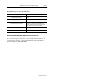
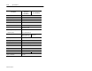
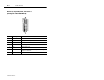
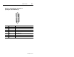
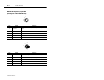
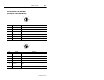
Table Of Contents
- Front Cover
- Important User Information
- Table of Contents
- Preface
- 1 - Scanner Features
- 2 - Installing Your Hardware
- Important Notes on Scanner Systems
- 1. Unpacking the Equipment
- 2. Setting the Address of the Base/Charger Unit
- 3. Connecting the Host Cable to the Base/Charger Unit
- 4. Mounting the Base/Charger Unit
- 5. Mounting the Power Supply
- 6. Connecting the Power Supply to the Base/Charger Unit and Power Receptacle
- 7. Connecting the Host Cable to the Host Device
- 8. Charging the Battery
- 9. Pairing the Scanner to the Base/Charger Unit
- 3 - Configuring Your Scanner
- 4 - Scanner Operation
- 5 - Maintenance and Troubleshooting
- A - Specifications
- B - Cable Pinouts
- C - Advanced Data Formatting
- Glossary
- Index
- Test Symbols
- Back Cover
Cable Pinouts B–5
Publication 2755-6.3
PS/2 keyboard. 6-pin Mini-DIN
(Catalog No. 2755-HCC-BP2-06)
4
6
5
3
2
1
Pin Signal Function
1 KEYBD DATA Actual data from the depressed key on the keyboard.
2 Not Used None
3 GND Ground
4 V BATT Power for device connected to this cable end.
5 KEYBD CLK Synchronous signal between the host and keyboard.
6 Not Used None
4
6
5
3
2
1
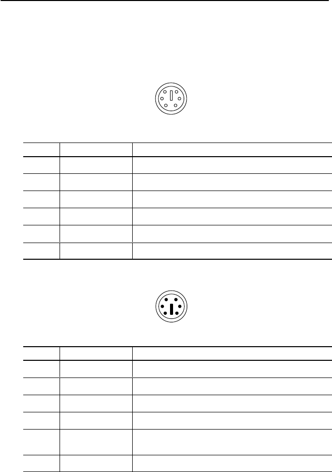
Pin Signal Function
1 DATA OUT Data is sent between the PC and the keyboard.
2 Not Used None
3 GND Ground
4 V BATT Power for device connected to this cable end.
5 CLK OUT
Computer sends clock pulse to keyboard to synchronize
keys.
6 Not Used None