
User guide
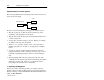
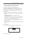
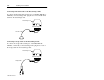
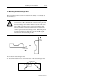
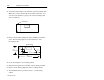
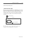
Table Of Contents
- Front Cover
- Important User Information
- Table of Contents
- Preface
- 1 - Scanner Features
- 2 - Installing Your Hardware
- Important Notes on Scanner Systems
- 1. Unpacking the Equipment
- 2. Setting the Address of the Base/Charger Unit
- 3. Connecting the Host Cable to the Base/Charger Unit
- 4. Mounting the Base/Charger Unit
- 5. Mounting the Power Supply
- 6. Connecting the Power Supply to the Base/Charger Unit and Power Receptacle
- 7. Connecting the Host Cable to the Host Device
- 8. Charging the Battery
- 9. Pairing the Scanner to the Base/Charger Unit
- 3 - Configuring Your Scanner
- 4 - Scanner Operation
- 5 - Maintenance and Troubleshooting
- A - Specifications
- B - Cable Pinouts
- C - Advanced Data Formatting
- Glossary
- Index
- Test Symbols
- Back Cover

2–8 Installing Your Hardware
Publication 2755-6.3
2. Attach the cable bracket to the underside of the base/charger unit.
Make sure you have attached the host interface cable first. You
can remove the bracket by prying it off of the base/charger unit
with a screwdriver.
Cable Bracket
3. Remove the mounting template from the installation instruction
sheet. The following figure shows the dimensions of the
base/charger unit.
Mounting Holes
0.875 in.
(22.23 mm)
1.5 in.
(38.1 mm)
4.75 in.
(120.65 mm)
9 in.
(228.6 mm)
4 in.
(101.6 mm)
1.5 in.
(38.1 mm)
1.75 in.
(44.45 mm)
4. Secure the template to the mounting surface.
5. Drill holes through the holes marked on the mounting template.
6. Remove the mounting template from the mounting surface.
7. Attach #10 flat-head or pan-head screws to your mounting
surface.