
User guide
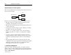
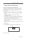
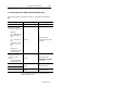
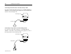
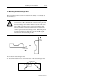
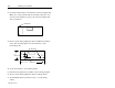
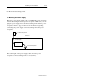
Table Of Contents
- Front Cover
- Important User Information
- Table of Contents
- Preface
- 1 - Scanner Features
- 2 - Installing Your Hardware
- Important Notes on Scanner Systems
- 1. Unpacking the Equipment
- 2. Setting the Address of the Base/Charger Unit
- 3. Connecting the Host Cable to the Base/Charger Unit
- 4. Mounting the Base/Charger Unit
- 5. Mounting the Power Supply
- 6. Connecting the Power Supply to the Base/Charger Unit and Power Receptacle
- 7. Connecting the Host Cable to the Host Device
- 8. Charging the Battery
- 9. Pairing the Scanner to the Base/Charger Unit
- 3 - Configuring Your Scanner
- 4 - Scanner Operation
- 5 - Maintenance and Troubleshooting
- A - Specifications
- B - Cable Pinouts
- C - Advanced Data Formatting
- Glossary
- Index
- Test Symbols
- Back Cover

Installing Your Hardware 2–5
Publication 2755-6.3
3. Connecting the Host Cable to the Base/Charger Unit
Use the appropriate host interface cable to connect the base/charger
unit.
Host Uses this cable type Catalog Number
DEC VT 2xx/3xx/4xx Wedge 2755-HCC-BV1-06
RS-232C devices that TxD
output on Pin 2, Female
connector. Examples include:
RB Module
PLC
R
model 5/11, 5/20,
5/30, 5/40L, 5/60L, or
5/80
SLCt model 5/03
➀
or
5/04
➀
RS-232C
2755-HCC-BR2-06
(TxD output on Pin 3, Male
connector.)
AB Workstation model
T-View
t
➀
, T70
➀
or
T71
➀
MessageViewt
➀
2755-DS/DD Enhanced
Decoder Host Port
RS-232C device that TxD
output on Pin 3, Female
connector. Example
includes:
RS-232C
2755-HCC-BR1-06
(TxD output on Pin 2, Male
2708-DH5 Workstation
Communications Port
(TxD output on Pin 2, Male
connector.)
IBM AT/XT and clones
Datalinert model DL 40
Wedge 2755-HCC-BP1-06
IBM PS/2 (and clones) model
30, 50, 55SX, 60, 70, or 80
Wedge 2755-HCC-BP2-06
➀
A 25-to-9 pin adapter is required to connect the host device to
the base/charger unit cable.