
Installation Instructions Manual
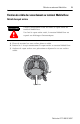

16 MobileView-Verbindungskabel
Publikation 2727-IN004C-MU-P
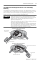
MobileView-Verbindungskabel
* Nur für den Anschluss an MobileView Guard G750-Terminals.
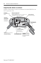
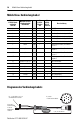
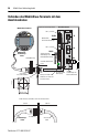
Diagramm des Verbindungskabels
K1, runder
17-Stift-Steck-
verbinder,
Stift-Nr.
MobileView-Ver-
bindungskabel
Drahtfarbe
K3,
11-Stift-
Buchse
S19
K2,
8-Stift-
RJ-45
Ethernet
Beschreibung
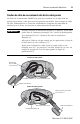
1 rosa -->> 6 – 24 V DC
2 schwarz -->> 7 – 0 V DC
3 grün-braun -->> 8 – Not-Aus, Stromkreis 1, positiv *
4 weiß-grün -->> 9 – Not-Aus, Stromkreis 1, negativ *
5 grau-rosa -->> 10 – Not-Aus, Stromkreis 2, positiv *
6 rot-blau -->> 11 – Not-Aus, Stromkreis 2, negativ *
7 braun -->> 1 – Aktivierungsschalter, Stromkreis 1,
positiv *
8 gelb -->> 2 – Aktivierungsschalter, Stromkreis 1,
negativ *
12 grün -->> 3 – Aktivierungsschalter, Stromkreis 2,
positiv *
17 grau -->> 4 – Aktivierungsschalter, Stromkreis 2,
negativ *
9 Brücke zu Stift 10 -->> – – Nicht verwendet
10 Brücke zu Stift 9 -->> – – Nicht verwendet
11 lila -->> 5 – Nicht verwendet
13 blau -->> – 1 TD+ (übertragen)
14 weiß -->> – 2 TD– (übertragen)
15 orange -->> – 3 RD+ (empfangen)
16 rot -->> – 6 RD– (empfangen)
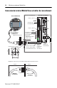
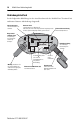
K2, 8-Stift-
RJ-45-Buchse
zu S4 am
MobileView-
Terminal
1
2
3
4
5
6
7
8
9
10
11
12
13
14
15
16
17
K3, 11-Stift-Buchse zu S19
am MobileView-Terminal
K1, runder
17-Stift-Steckverbinder
5, 10, 15 oder 20 mm